A pin-compatible op-amp passes the bench test, then drifts
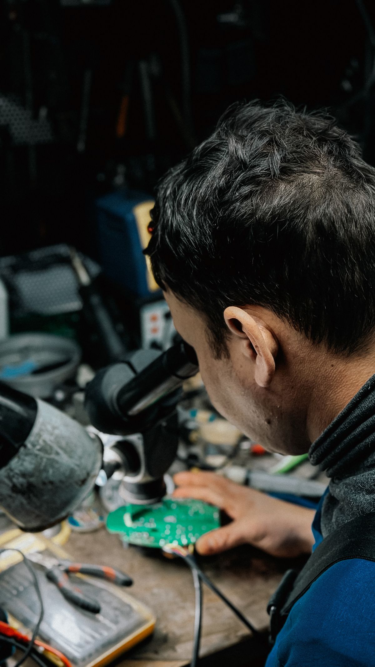
Illustrative image: Bulat843 🌙 on Pexels
Fictional engineering case. No real company or reader is being quoted.
Previous problem: The motor reverses. The CAN network drops out..
Last week’s answer: the CAN bus fault
Two effects overlapped in this fictional case: reflections from the long branch and motor-related common-mode interference. A correct DC resistance reading did not prove either was absent. The team measured differential and common-mode waveforms at the failing node, then shortened the branch and rerouted it away from the motor leads in separate tests. Shortening reduced ringing; rerouting reduced commutation-related disturbances. Appropriate shield bonding completed the repair. Termination remained at the two physical bus ends, not every branch. The network was retested at its original bitrate under repeated reversals. The exact allowable stub length and voltage limits depend on the transceiver and timing budget.
Technical background: Texas Instruments’ CAN physical-layer application report.
This week’s problem: the pin-compatible op-amp
A manufacturer has approved an alternative operational amplifier after the original device entered extended lead time.
The replacement uses the same package and pinout. Its supply-voltage range, nominal input-offset voltage, gain-bandwidth product and operating-temperature rating all appear suitable. Initial bench testing also passes.
The device is used in a high-impedance analogue front end that conditions a resistive sensor before a 16-bit ADC. After approximately 30 minutes at normal operating temperature, the measurement develops a repeatable positive error. At the upper end of the sensor range, some units approach the ADC limit and lose measurement headroom.
The error disappears when the original op-amp is refitted. Recalibrating the replacement at room temperature temporarily hides the problem, but the error returns as the board warms.
The purchasing record describes the two parts as compatible, and the comparison table contains the headline specifications. It does not compare the full temperature curves or the conditions under which those figures were measured.
The design team has checked the supply rail and found no obvious instability. It now needs to determine whether the error comes from input-offset drift, bias current flowing through the sensor impedance, restricted common-mode range, output swing, PCB leakage or some combination of these effects.
What should the team test first?
Which measurements would separate the op-amp’s internal temperature behaviour from leakage or contamination on the assembled PCB?
Would you begin by measuring input-offset drift, input bias current, common-mode headroom, output swing or the voltage developed across the sensor’s source impedance?
Next week’s Troubleshooter will explain what the fictional team found and why a component described as “pin compatible” was unsuitable at the actual operating point.
Readers can submit their own design, sourcing or production problems through the Troubleshooter page.