Choosing an alternative electronic component: six checks before approving the swap
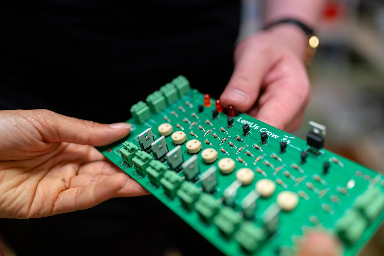
Illustrative image: ThisIsEngineering on Pexels
The phrase "drop-in replacement" is doing quite a lot of work in a component shortage. To a buyer it can mean an order that gets production moving again; to an engineer it should mean a candidate whose compatibility has been established for a particular design. Those meanings need to meet somewhere before the parts reach the assembly line.
Cross-reference tools and parametric searches are useful for finding candidates, but their output cannot explain every reason the original designer selected a device. A regulator may have been chosen for its behaviour during start-up, a connector for its particular mating arrangement or a capacitor for its effective value under bias. If the selection record consists of little more than a BOM description, some of that reasoning will have to be reconstructed.
The following checks give the comparison a manageable order. They are intended to help reject poor candidates early and define the work on promising ones, rather than turn every substitution into an open-ended research programme.
1. Establish what the circuit needs from the part
Begin with the application rather than the replacement's best-looking specification. The useful requirements are the conditions the component must tolerate and the performance the product needs, including relevant start-up, shutdown and abnormal conditions. For a regulator, this could mean supply variation, loading, transient response and thermal conditions; a programmable device brings firmware behaviour and production programming into the discussion as well.
It is worth distinguishing a genuine requirement from an incidental capability of the original part. Requiring every characteristic of the old device can exclude a perfectly workable candidate, while copying only the short description can omit the very behaviour on which the circuit depends. Reviewing the schematic, existing qualification evidence and representative measurements helps resolve that ambiguity.
When a requirement cannot be established confidently, keep it visible as a question to answer. It is much harder to recover an unstated assumption after purchasing has interpreted a preliminary comparison as approval.
2. Read past the familiar part number
TI's LM1117 and TLV1117LV illustrate how apparently related names can conceal differences that matter to a substitution review. The LM1117 datasheet specifies an output-capacitor ESR range of 0.3 Ω to 22 Ω in its capacitor-selection guidance, whereas the TLV1117LV is designed for ceramic output capacitors and has a different recommended input-voltage range. [1][2]
| Datasheet check | LM1117 | TLV1117LV |
|---|---|---|
| Recommended input-voltage limit | Up to 15 V, subject to the relevant operating conditions | 2 V to 5.5 V |
| Output-capacitor requirements | Specified capacitance and ESR requirements | Ceramic capacitor requirements |
| Exact device | Check voltage, grade and package option | Check voltage and package option |
These selected differences do not establish interchangeability. They show why the full datasheets and orderable numbers are needed before deciding whether a comparison is worth pursuing.
For a circuit fed from 12 V, a candidate with a recommended input limit of 5.5 V is unsuitable regardless of its other attractions. At a compatible supply voltage, the capacitor network still needs assessment. A catalogue search might have brought both devices into view without making either decision for the engineer.
The distinction between recommended operating conditions and absolute maximum ratings matters throughout this exercise. A stress limit does not promise normal operation, and a typical performance curve does not necessarily guarantee the worst-case limit the product requires. Compare the conditions attached to the numbers before comparing the numbers themselves.
3. Check the surrounding circuit, including the less glamorous parts
A MOSFET's on-resistance becomes a useful comparison only when its gate voltage and temperature conditions are relevant to the board. Nexperia's interactive datasheet material shows these dependencies separately from gate-charge information, which also matters to the switching circuit. [3] A device with an appealing resistance at a gate voltage the driver cannot provide may be an entirely unhelpful substitute.
The same attention belongs on passives. Murata explains that the effective capacitance of certain ceramic capacitors decreases with applied DC voltage. [4] Two nominally identical capacitance values can therefore require a closer look at the characteristic data, particularly where the circuit relies on retaining a minimum capacitance in service.
There is no benefit in collecting every possible difference without judging its significance. The engineer's contribution is to connect a difference with the behaviour it might change: whether a rail remains stable, a driver can switch the device as intended or the assembly retains the required thermal margin. That reasoning is what makes the resulting test plan useful.
4. Decide whether the existing assembly can use it
Package names are a convenient starting point, but the package drawing and pin functions have the final say. Check dimensions, height, connections and any exposed-pad requirements against the released board and manufacturing process. A component can fit the available space while still requiring changes to the footprint or assembly instructions.
For programmable devices, a similar peripheral list is only the beginning of the compatibility assessment. Memory arrangements, boot behaviour, relevant errata and peripheral operation may affect the software or production test. An alternative that requires those changes could still be a good choice, provided the change is costed and scheduled as such.
This is the point at which the business should be able to describe the proposal sensibly: an alternative for the existing assembly, a change with limited modifications or a more substantial redesign. Using one convenient label for all three makes planning unnecessarily difficult.
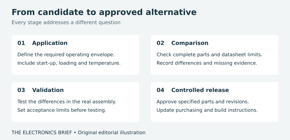
5. Test the differences under conditions that could expose them
A bench demonstration can be encouraging without being sufficient evidence for release. If the uncertainty concerns start-up, examine the supply ramps and loads that matter to the product; if it concerns heat, use a representative assembly and operating conditions. Changed switching behaviour may justify further waveform measurements and an assessment of whether EMC checks need repeating.
The acceptance limits should be agreed before the results arrive. Otherwise a borderline result can become progressively easier to accept as the shipment date approaches, without any new technical evidence to explain the change of view.
The extent of validation should follow the application and the nature of the substitution. A change in a safety-related function brings different obligations from one in a simple indicator circuit. Engineering and quality should agree which product, customer or approval requirements are affected rather than automatically repeating everything or assuming that nothing needs repeating.
6. Make the approval usable by the people placing orders
An approved alternative needs an exact identity and a scope. State the manufacturer and orderable part number, the assembly revisions covered and any restrictions, including whether use is limited to a particular build. Purchasing should not have to interpret an engineer's old email to discover whether a candidate was ever released.
The controlled manufacturing data must agree with that decision. If a concession allowed one batch, it should not become permanent approval merely because the same substitution worked last time. Where unrestricted use is intended, complete the release and make the evidence available to the manufacturing partner as well as the internal team.
Finally, check whether the effort has improved the supply position. An electrically suitable replacement that is equally difficult to obtain may not solve the commercial problem that prompted the work. A useful alternative is one the product can use, the organisation is authorised to fit and purchasing has a credible route to buy. Getting that combination in place before a shortage is considerably easier than assembling it while a customer waits.
Sources
[1] Texas Instruments, LM1117 datasheet, revision Q, sections 7 and 9.
[2] Texas Instruments, TLV1117LV datasheet, revision C, sections 6 and 8.