Same rating, hotter enclosure: investigate the DC-DC swap
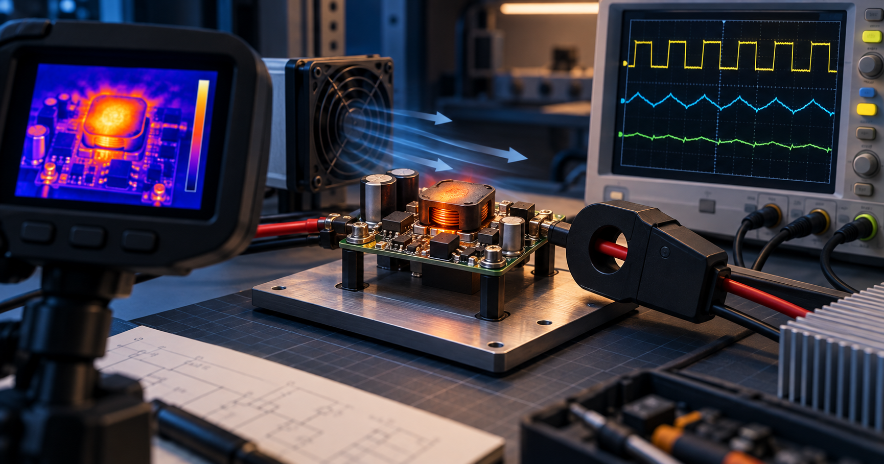
Illustration created for The Electronics Brief.
Fictional engineering case. No real company or reader is being quoted.
Previous problem: The boards pass test. Then the capacitors crack..
Last week’s answer: the cracked MLCCs
The pattern made board strain during enclosure assembly a leading hypothesis. It did not, by itself, exclude earlier placement damage, depanelisation stress or a component defect.
Every board passed automated optical inspection, in-circuit test and final functional test. The shorts appeared later, after installation in the enclosure, and the affected capacitors were concentrated near mounting points and panel break-off edges. That distribution was the strongest clue.
Multilayer ceramic capacitors are strong under compression but comparatively vulnerable to bending stress. Flexing the PCB can initiate a crack through the ceramic body or its termination. A small crack may remain electrically invisible during production test and become conductive later as temperature cycling, moisture or electrical bias changes the damaged region.
Before removing the capacitors, the investigation recorded the precise position and orientation of every failure, visible damage, enclosure screw sequence and torque, standoff positions, depanelisation method, lot information, and electrical leakage before disturbing the board.
The most useful controlled experiment instrumented the board with strain gauges close to the affected MLCC positions and measured strain during depanelisation and enclosure assembly. Repeating the build with different screw torques, assembly sequences and board supports identified the operation producing the highest measured strain; that result still needed to be correlated with examination of the failed parts.
In this fictional case, the highest strain occurred when the enclosure screws were tightened in sequence. The board was pulled against a slightly misaligned standoff, concentrating flex around two mounting points. Microscopy and cross-sections of failed parts then confirmed cracks consistent with flex damage. Component orientation relative to the measured strain helped explain the failure pattern; orientation alone would not have established the cause.
Corrective action included aligning the standoff, controlling screw torque, reviewing component orientation and considering flexible-termination MLCCs in the highest-risk positions. Passing an electrical test did not prove the assembly was mechanically sound.
Technical background: Murata’s guide to strain cracks in MLCCs.
This week's problem
A manufacturer replaces an obsolete isolated DC-DC converter with a pin-compatible module carrying the same nominal input, output and power rating. On the open bench, the new module delivers the required load and records 89% efficiency, close to the previous part.
Inside the sealed product enclosure, its case temperature rises rapidly. After approximately twenty minutes at full load and 40°C ambient, the output begins to cycle. Thermal protection is suspected, but undervoltage lockout and other protection modes still need to be excluded. The previous converter passed the same product test.
The replacement datasheet quotes its headline efficiency at a different input voltage. Its derating graph is given for natural convection on a specified test board. The production PCB has a copper keep-out beneath the module because of an isolation requirement, and the enclosure has no forced airflow. Input ripple current is also higher than it was with the original part.
Question: What is the most likely combination of causes, and which measurements would you make before changing the PCB or enclosure?
Consider conversion loss at the actual operating point, thermal resistance through the pins and PCB, copper area, input ripple, airflow assumptions, switching frequency, surrounding heat sources and the way case temperature is being measured.
The answer will appear in next week's Troubleshooter.