The motor reverses. The CAN network drops out.
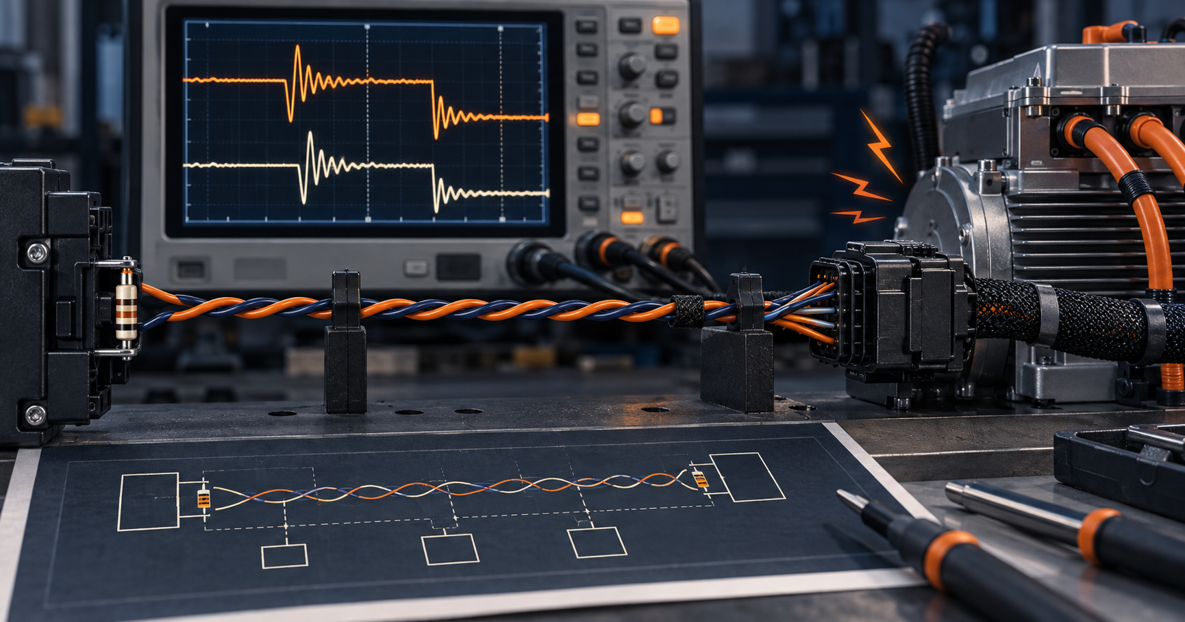
Illustration created for The Electronics Brief.
Fictional engineering case. No real company or reader is being quoted.
Previous problem: Same rating, hotter enclosure: investigate the DC-DC swap.
Last week's answer
The open-bench efficiency result did not establish that the replacement would run safely in the enclosure. In this fictional investigation, measurements at the actual operating point and confirmation of the module’s protection behaviour supported a thermal explanation. At the product's actual input voltage and load, conversion loss was higher than the headline figure implied. The replacement also relied more heavily on heat transfer through its pins into board copper, while the product PCB's isolation keep-out removed much of that path. The supplier's derating curve assumed a test board and natural-convection environment that the sealed enclosure did not reproduce. Higher input ripple was a reason to measure capacitor RMS current and estimate ESR heating. It did not, on its own, prove greater internal module loss; input/output power measurements were needed for that comparison.
The correct investigation was to measure input and output power at the operating point, ripple current, case and pin temperatures, local ambient, airflow and thermal gradient into the PCB. A suitably attached temperature sensor provided a case-temperature measurement. Thermal imaging could help locate hot spots, provided emissivity and reflections were handled correctly; a camera was not essential. The eventual fix might involve a different module, more copper outside the isolation boundary, reduced load, input filtering or a change to enclosure cooling; a larger heatsink alone would not address every cause.
Technical background: RECOM’s guide to converter datasheet parameters.
This week's problem
An industrial controller uses a 500kbit/s CAN network with two 120-ohm end terminations. The bus resistance is correct when powered down, and communication is stable while the machine is idle.
Whenever a reversible motor changes direction, one node on the longest branch records error frames and occasionally becomes bus-off. The transceiver and cable have already been replaced. The branch is 1.8m long, passes through the same cable tray as the motor leads and uses a connector where the shield is continued through a short pigtail.
An oscilloscope at the controller shows ringing after dominant-to-recessive edges. At the failing node the common-mode voltage also moves sharply during motor commutation. Reducing the bitrate makes the fault less frequent but does not remove it.
Question: Which observations point to signal-integrity trouble, which point to coupled noise, and how would you separate the two causes without masking the fault?
Consider branch length, termination placement, probe location, shield bonding, cable routing, transceiver common-mode range, ground offset and the inverter's switching edges.
The answer will appear in the following Troubleshooter.