Why a working prototype can fail in production
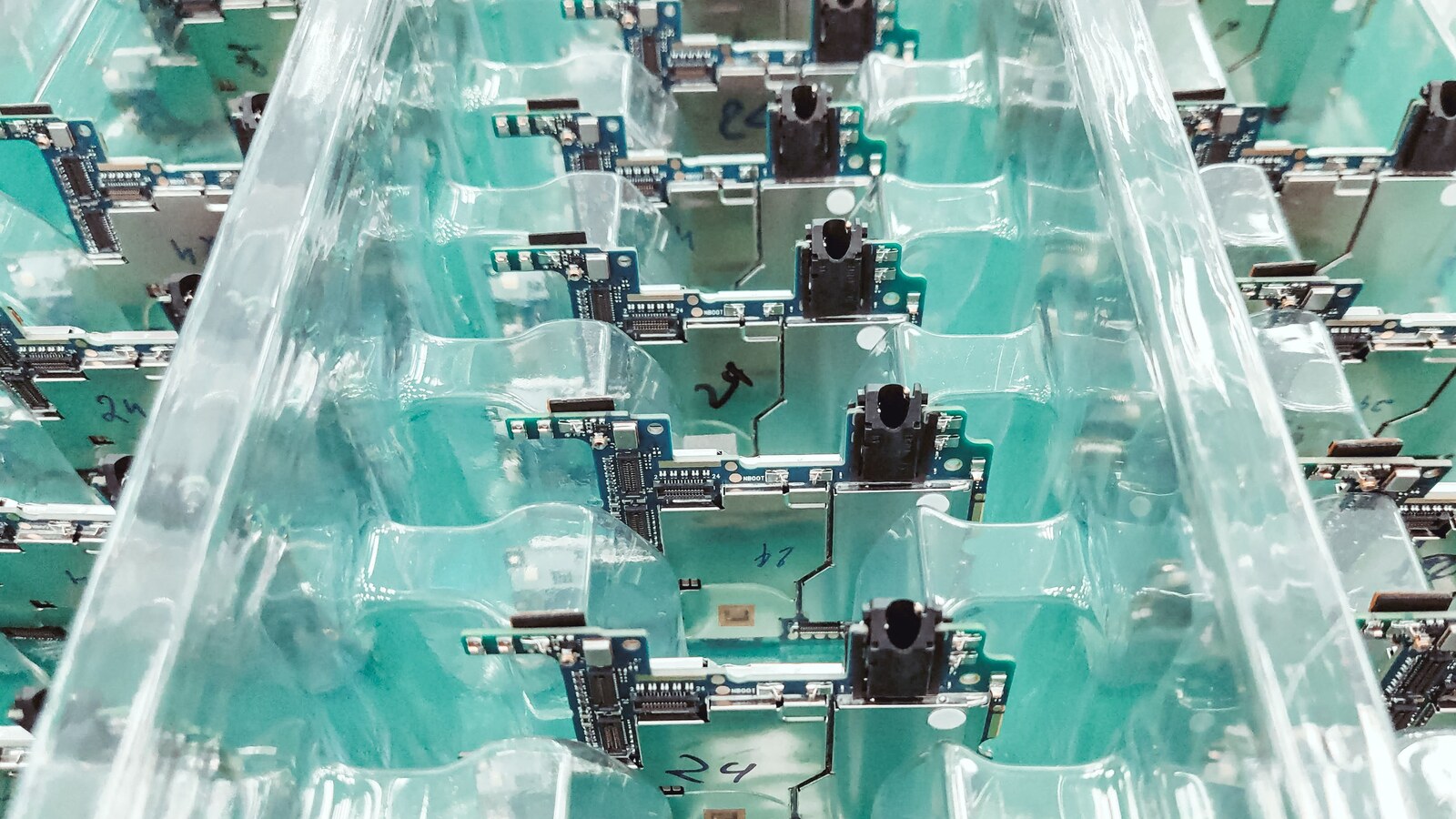
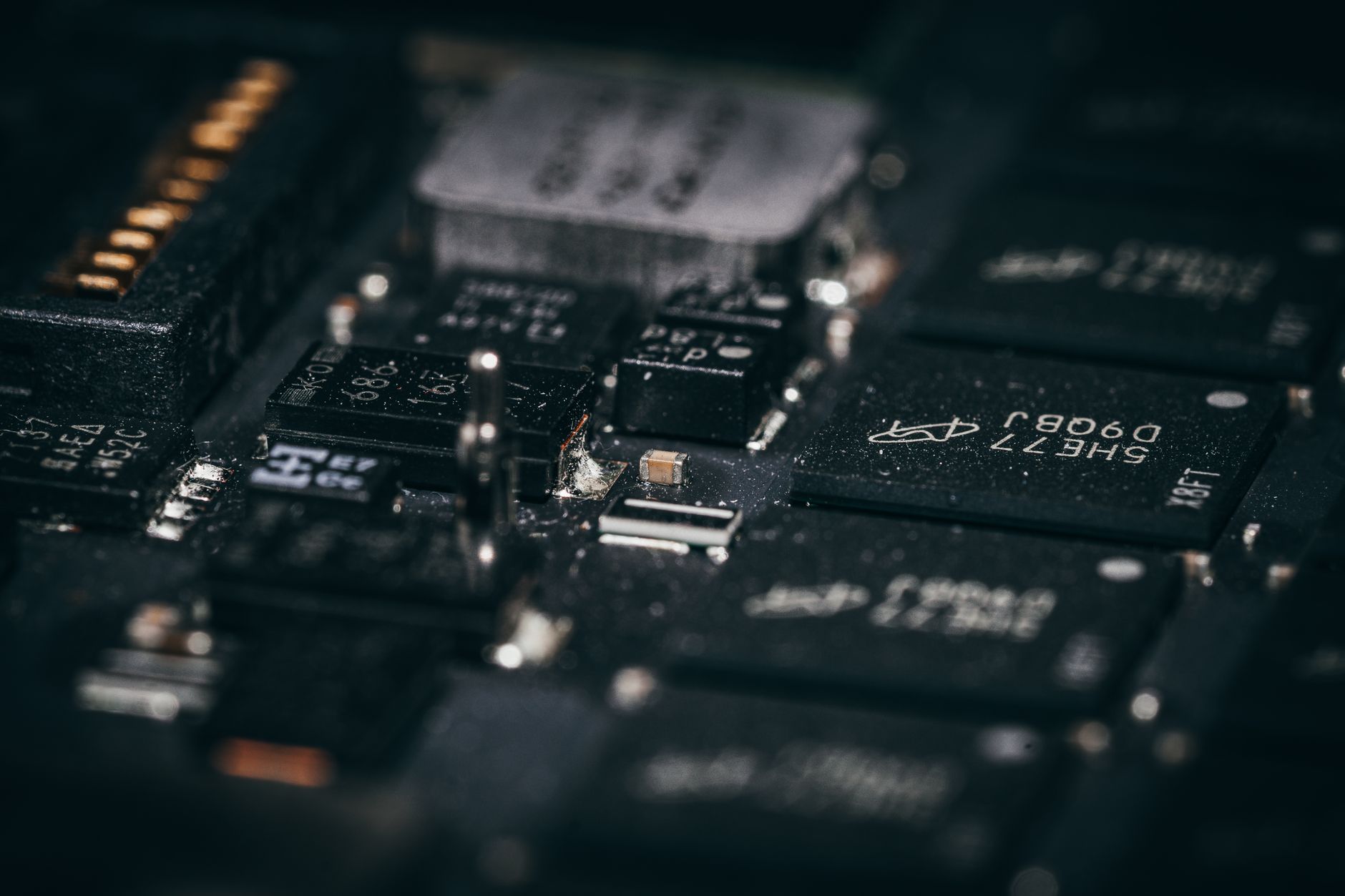
Photo by Andrey Matveev on Pexels. Cropped from the original.
The prototype powers up, the demonstration runs and the project appears ready to move.
Then the first production batch produces intermittent start-up failures, an unexpected test yield problem or a fault that nobody saw on the engineering bench.
This is not necessarily evidence that the prototype was misleading. It may have answered a narrower question than the production team assumed.
A prototype can show that a design is possible. It does not, by itself, show that the design is repeatable.
One working unit does not explore tolerance
The components on a prototype occupy particular points within their allowed tolerances. The power supply starts at one voltage, the oscillator has one actual frequency, the sensors have one offset and the passives happen to combine in one way.
Production introduces the rest of the permitted population.
Problems appear when a design works around typical values but has insufficient margin at the corners. Timing, analogue gain, threshold voltages, power sequencing and thermal performance are common places for these assumptions to surface.
Simulation and worst case analysis help, but the underlying component models and environmental assumptions need scrutiny. A calculation built from typical figures can reproduce the same false confidence as a single prototype.
Hand assembly can conceal process sensitivity
Prototype boards are often assembled slowly, inspected closely and repaired by experienced technicians. Components may be placed by hand, soldered individually and cleaned differently from the intended production process.
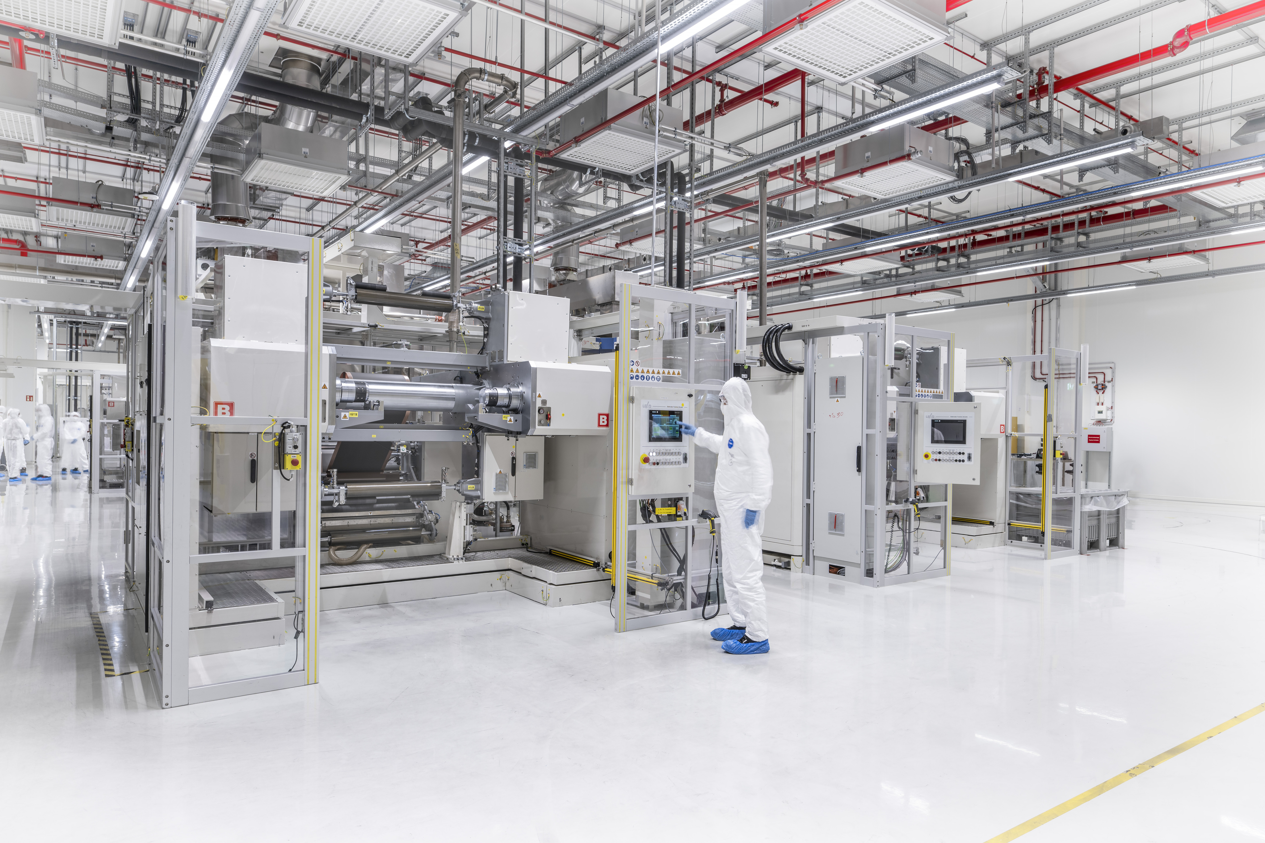
Volume assembly introduces paste printing, placement tolerances, reflow profiles, automated inspection, panel handling and depanelisation. Each process is controlled, but none is identical to an engineer working on one board.
A footprint that can be made to work by hand may have poor process margin. Large thermal imbalances, unsuitable paste apertures, inaccessible joints and components placed too close to the board edge may not reveal themselves until the production line is involved.
This is why design for manufacture, assembly and test are separate reviews. IPC describes them as principles that help make boards easier to manufacture, assemble and test while reducing cost and improving the chance that the finished product works as expected.
The prototype may contain parts production will not use
An engineering build may use available package variants, laboratory modules or components bought in small quantities. By the time production begins, the specified part may have a long lead time, a minimum order problem or a different approved source.
A substitution can be electrically reasonable and still alter start-up, thermal behaviour, electromagnetic compatibility, firmware or manufacturing yield.
The approved production BOM should therefore be tested as a configuration. A prototype assembled from convenient parts is not automatically representative of that configuration.
Bench conditions are usually kinder
Laboratory supplies are stable, cables are short and ambient temperature is comfortable. Enclosures may be open and the product may run for minutes rather than days.
The production unit must work with its real supply, harness, enclosure, load, cooling path and user behaviour. It may also need to start at temperature extremes, recover from brownouts and tolerate events that were absent during development.
Thermal problems are particularly good at hiding. A board that operates in free air may lose its margin when placed in a sealed enclosure beside other heat sources. Component self-heating can then change electrical behaviour as well as lifetime.
Undocumented modifications do not reach production
Prototype development frequently produces small corrections: a changed resistor, cut track, added capacitor, bodge wire or firmware setting.
The danger is not the modification. The danger is a modification that exists only on the working unit.
Before release, reconcile the schematic, PCB, BOM, firmware, programmable device files and configuration data with the actual prototype. Photographing or retaining a golden unit is useful, but it cannot replace controlled design records.
A functional test may miss the failure
A prototype is usually tested by engineers who understand how it should behave. Production needs a defined method that can distinguish a good unit from a faulty one repeatedly and within the available time.
Functional testing alone may confirm outputs without identifying marginal solder joints, incorrect component values or untested interfaces. Conversely, a test designed without regard to normal tolerances may reject acceptable products.
IPC’s work on design for test makes the distinction clearly: manufacturing test is intended to establish that the product has been built correctly. Test points, programming access, fixture clearances and diagnostic functions must therefore be designed into the product rather than added after layout.
Firmware and calibration are part of the build
Production failures are not confined to hardware.
The wrong firmware image, bootloader, option setting, security key or calibration data can make correct boards appear faulty. Programming order can matter where fuses or security settings restrict later access.
The release package should define the approved software version, programming method, verification step and treatment of unit specific data. If calibration is required, specify the equipment, conditions, limits and record retained for each unit.
The pilot build is an engineering experiment
The safest bridge between prototype and volume production is a controlled pilot using the intended manufacturer, data, components, tooling, software and test process.
Its purpose is not merely to deliver a small quantity early. It should expose assumptions.
Record assembly defects, test failures, repair time, component substitutions and operator questions. Review the distribution of measurements rather than only the pass count. A batch in which every unit passes but several sit close to a limit is giving useful warning.
Production readiness is reached when the product and process are both controlled. The question is no longer whether an engineer can make the design work. It is whether the documented design can be built repeatedly by the intended process and still meet its requirements.
Technical references: Global Electronics Association on DFM, DFA and DFT; IPC design for test technical paper; IPC board design standards.