Your board works on the bench. Why does it fail EMC testing?
A prototype can work reliably on the bench and still fail EMC testing because the laboratory is measuring behaviour that functional tests may never have exercised. Production cables introduce new current paths, the enclosure changes how fields couple and a particular operating mode can expose a source that was quiet during development.
There is nothing contradictory about the two results, although it can feel that way when the board has already completed weeks of testing. The useful question is what changed between those arrangements and which part of the product now accounts for the failure. A cable carrying a small RF current may matter more to the emissions result than the component producing the strongest local field.
The failed test defines the investigation
Emissions and immunity failures lead in different directions. An emissions result describes energy leaving the product through radiation or connected wiring; an immunity result describes its response to an applied disturbance. A reset during an immunity test therefore needs a different evidence trail from a peak above an emissions limit.
For emissions, that trail includes frequency, level, detector, bandwidth and limit alongside the operating mode and test configuration. For immunity, the applied disturbance, its level, the affected port and the observed response establish what needs reproducing. A communication error and a drifting analogue reading may have different causes even when the same stimulus triggers them.
The laboratory’s selected requirements and configurations matter too. Cable lengths, terminations, enclosure bonding, load and firmware can all affect the result, so photographs and a record of the failing arrangement are valuable when the prototype returns to the bench. Even a seemingly helpful tidy of the wiring can remove the condition the investigation needs.
How PCB noise reaches an external cable
Clock harmonics and switching edges provide recognisable patterns that can help locate an emissions source. A peak that moves when a clock or converter setting changes points towards a relationship, although the adjustment may affect more than one mechanism.
The route from that source to the radiating structure is just as important. Common mode RF current on an external cable can contribute more to the measured emission than a strong local field beside an IC. Tektronix’s guidance on preliminary EMC testing brings near field probing, cable current measurements and antenna observations together because they reveal different parts of this route. [1]
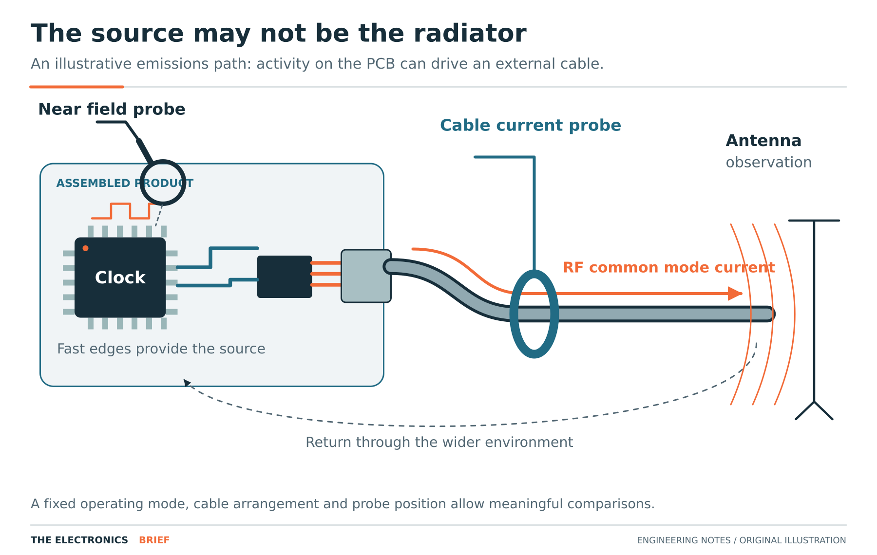
Near field measurements are particularly sensitive to probe position and orientation. A fixed arrangement makes comparisons useful; otherwise a change in the reading may come from moving the probe rather than modifying the circuit. The distinction becomes expensive when a promising bench result cannot be repeated at the laboratory.
Return paths and switching loops influence the result
Plane gaps, connector transitions and changes of layer can interrupt the relationship between a fast signal and its reference. That changes loop inductance and the distribution of return current, allowing connections labelled ground on the schematic to behave differently during an edge. Analog Devices’ grounding guidance discusses reference plane impedance and the physical routes taken by analogue and digital currents. The recommendations for the particular devices help translate those principles into a layout review. [2]
Switching converters add branches whose current changes rapidly as the switches change state. Their physical loop areas affect emissions, while nodes with high dv/dt can couple into nearby conductors. TI’s layout guidance distinguishes those mechanisms from the routing of sensitive control traces. A large copper area at a switch node, for example, can increase capacitive coupling even though it offers low DC resistance. [3]
The relevant loop depends on topology, which is why a layout recommendation for a synchronous buck cannot simply be transferred to a boost converter.
A temporary modification can test the suspected path
A clamp-on ferrite can help establish whether a cable is involved in an emissions problem. Its effect depends on frequency, impedance and installation, so a reduction supports the suspected coupling path without yet identifying a suitable production part or demonstrating sufficient margin.
Changes to shield bonding, local capacitance and edge rate can be used in the same way. Changing one factor at a time makes the result easier to interpret, while a scan across the spectrum and other operating modes reveals whether the apparent improvement has moved the problem elsewhere.
For an immunity failure, a capture of the first electrical symptom can separate possible causes. A reset may follow a supply disturbance, activity on the reset pin or an execution fault; recording those signals alongside the applied event narrows the investigation before components are changed.
The measurement connections are part of this arrangement. Long probe ground leads can pick up switching energy or introduce resonance, and an instrument connection can alter the common mode path. Tektronix’s probing guidance explains why connection geometry and probe selection affect the voltage captured in a power circuit. [4]
What the retest needs to establish
Once the suspected mechanism has been addressed, the complete product can be tested again under the original failing conditions and the other required supply, load, cable and software configurations. An improvement measured locally helps guide that work, while formal compliance remains a result of the applicable test on the complete product.
The engineering record is more useful when it connects the modification to the observed mechanism. An enclosure bonding point or harness route may change again during production, and knowing why it affected the result gives that later review something substantial to work from. A component list alone rarely carries the whole explanation.