Debugging a JTAG chain with the BSDL file
A JTAG chain that returns the same unexpected IDCODE on every scan needs a different investigation from one whose results change each time. A repeatable value may point to a device or file mismatch, while changing results raise questions about electrical conditions or chain configuration. The raw scan results preserve that difference, which can be lost in a tool’s final error message.
The BSDL file describes the device’s boundary-scan implementation, including its instruction register, boundary register, supported instructions and package pin mapping. The test system uses that description to check the hardware, so a syntactically valid file for the wrong device or package can still produce a mismatch. [1]
Establish which chain is actually connected
Start with the assembled board revision and fitted population. Trace TDI through each device to the final TDO connection, including any buffers, links, multiplexers or selectable subchains. Compare that route with the test project before interpreting an unexpected device count as a failed component.
Power and mode settings belong in the same record. A device that is unpowered, held in an unsuitable reset state or missing its boundary-scan compliance conditions can interrupt the expected chain. Check the target I/O voltage, controller reference and the relevant reset and strap pins against the component documentation. [2]
The TAP reset sequence also has to reach every participating device. TRST, where implemented, resets test logic; it should not be assumed to be interchangeable with the board’s processor reset. The controller’s initialisation must suit the actual hardware arrangement. [3]
Count devices before interpreting their identities
A conventional IEEE 1149.1 device has a one-bit BYPASS register. With every participating device in BYPASS, a shifted test pattern can establish the number of serial stages between TDI and TDO. XJTAG uses this as an early chain check, before comparing the longer device registers. [4]
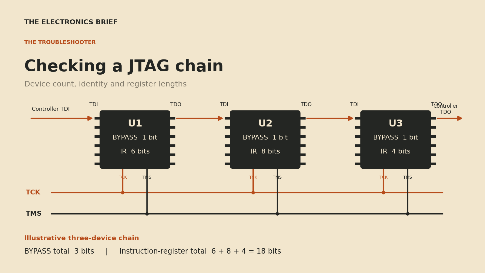
An illustrative chain of three devices would contribute three bypass bits to the data path, even if one of the fitted parts were the wrong component. Conversely, an unexpected count can arise from a link setting or an inaccessible device as well as a broken solder joint, so the count needs to agree with the actual route before it can help identify the fault.
Activity at the connector’s TDO pin is not enough to clear the whole chain. XJTAG notes that the final device can still shift data when an earlier device is malfunctioning, provided the final device receives TCK and TMS. A repeated scan gives the oscilloscope a useful trigger while the signal is followed from one device to the next. [2]
Match a stable IDCODE to the correct file
Where a device implements an IDCODE register, its 32-bit value contains manufacturer, part and revision information. IDCODE is optional for conventional IEEE 1149.1 devices, so the absence of a 32-bit identity is not automatically a failed device. The tool needs to interpret the chain using the relevant device descriptions. [1][4]
If the returned code is stable, compare it with the original manufacturer’s BSDL for the fitted silicon and package, recording which fields differ. A revision mismatch narrows the investigation to a newer file or documented revision compatibility, while a manufacturer or part-number mismatch calls the device identity itself into question.
Changing the expected code simply to make the test pass removes evidence. XJTAG’s guidance treats manual edits as a last resort, with particular care around revision masks. Manufacturer and part-identity bits must not be altered to conceal a different device. The corrected file and the supplier’s explanation should remain with the released test project. [2][5]
Use register lengths to test the description
Once identities are understood, compare the measured instruction-register length with the sum of the participating devices’ declared lengths. A hypothetical chain with 6-, 8- and 4-bit instruction registers would therefore have a total instruction-register length of 18 bits. [4]
The boundary register is a separate check. Its length and cell functions come from the BSDL and its cells do not map one-for-one to package pins. A bidirectional pin can involve several cells, while other pins may not be boundary-scan accessible at all. Counting package leads is therefore not a useful substitute for the declared register. [1][6]
A chain can pass an identity read and still fail the register comparison. The result can indicate a wrong file, the wrong instruction or a device that has not entered the expected test mode. Before moving to interconnect tests, check the file’s compliance-pin requirements against the actual strap and reset states. Device manuals and errata remain the authority when the BSDL leaves those conditions unclear. [5]
Separate timing faults from a repeatable mismatch
Repeat the scan at a lower TCK rate, keeping the other settings unchanged. If the returned identities or register lengths become reliable, investigate timing and signal integrity rather than changing the file to match the earlier corruption. XJTAG specifically recommends examining signal integrity when failures disappear at 100 kHz. [2]
Inspect TCK at the receiving devices and TDO at the point where the controller samples it, using the relevant ground reference. Cable length, buffer delay and reflections can change the waveform that reaches the pin. Termination needs to suit that route and the controller’s output characteristics, so a resistor value copied from another board is only a starting point. [7]
Fixture wiring can be responsible even when the PCB routing is sound. Keeping each signal close to its return reduces loop area; a distant common ground lead leaves the scan signals exposed to a much larger loop. XJTAG’s fixture guidance recommends nearby ground connections and signal/ground pairs, with particular attention to TCK. [8]
Record what resolved the failure
A stable chain check establishes communication with the expected scan logic under the tested conditions, allowing subsequent interconnect tests to use that chain to investigate the assembly. Their coverage and acceptance criteria still need to be defined, since communication with the scan logic cannot establish the state of every board net or predict the result of a functional test.
For the fault record, retain the fitted board revision, BSDL revisions, chain configuration, test clock and raw results alongside the waveform or voltage measurement that resolved the failure. If the same board later fails only in a production fixture, that record gives the comparison a known starting point.
Sources
- XJTAG, BSDL contents, pin mapping and optional IDCODE implementation
- XJTAG, debugging chain-check failures, repeated scans and identity mismatches
- XJTAG, TAP signals and boundary-scan operation
- XJTAG, device count, IDCODE and register-length checks
- XJTAG applications engineer William Robinson, BSDL mistakes and compliance conditions, 22 October 2025
- XJTAG, detailed BSDL and register descriptions
- XJTAG, testability, clock routing and termination considerations
- XJTAG, signal integrity and return paths in test fixtures
Illustrative three-device JTAG chain with shared TCK and TMS, three bypass bits and instruction-register lengths of 6, 8 and 4 bits. Diagram: The Electronics Brief. Image source.