Choosing a DIN-rail enclosure before the PCB layout becomes expensive
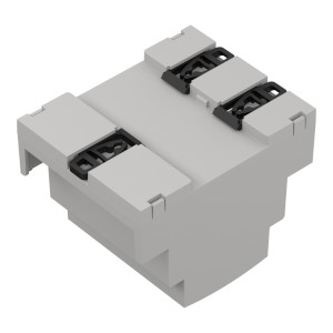
A DIN-rail housing can look like a straightforward mechanical purchase until the terminal blocks, board supports and lid all demand the same few millimetres.
TME’s expanded coverage of Kradex enclosures provides a useful starting point for examining that problem. The range includes modular DIN-rail housings, matching circuit boards, terminal covers, blanks and other accessories. Treating those parts as a complete assembly changes the order in which the enclosure should be selected.
The Kradex ZD family spans housings from two to twelve modules, including ABS versions with a UL 94 V-0 material classification. Other Kradex families available through TME include sealed universal housings and handheld enclosures. Their protection claims belong to those specific products; they should not be carried across to the DIN-rail range. [Source 1]
Start with the assembled dimensions
The external width establishes how much rail space the product occupies. It does not establish the usable PCB width or the clearance above a mounted component.
Kradex’s ZD1004J illustrates the difference between buying a box and defining an assembly. The manufacturer lists the housing dimensions, material and compatible accessories, including end blanks and terminal-aperture covers. The enclosure is supplied without a gasket. Those details need to be considered together with its mechanical drawing. [Source 2]
Before fixing the board outline, place the proposed terminal blocks and tallest components in the housing model. Include the way the lid closes and the space needed to insert or remove the board. A component can fit inside the final volume yet obstruct assembly.
Terminal access deserves its own check. The connector pitch, aperture position and wiring direction must agree. So must screwdriver access and the path taken by the cable after it leaves the terminal.
| Selection point | Detail to resolve before layout is fixed |
|---|---|
| Board mounting | Support positions, board thickness and insertion path |
| Terminals | Pitch, aperture alignment and tool access |
| Front panel | Display, indicator and control clearances |
| Complete assembly | Required covers, blanks, clips and rail mounting parts |
Keep protection and flammability separate
UL 94 V-0 describes a material’s behaviour in a specified flammability test. It is not an ingress-protection rating or approval of the complete electronic product. UL also identifies material thickness and the intended application as relevant to interpreting its classifications. [Source 3]
Ingress protection concerns the enclosure assembly and its openings. A claim for a sealed housing cannot be assumed to survive a new connector cut-out, an unsuitable gland or a change to the cover arrangement. Enclosure and accessory evaluations therefore need to match the actual construction. [Source 4]
Thermal clearance is another independent constraint. Space around a component does not establish that its temperature will remain acceptable once neighbouring modules, wiring and cabinet conditions are included. That requires the product’s thermal assessment.
The enclosure bill of materials should consequently identify more than the main moulding. Include the exact cover, terminal shields, blanks and mounting parts, then keep the approved mechanical drawing with the PCB release. That gives manufacturing a defined assembly rather than a housing part number followed by several assumptions.