What a thermal test vehicle can prove before the processor exists
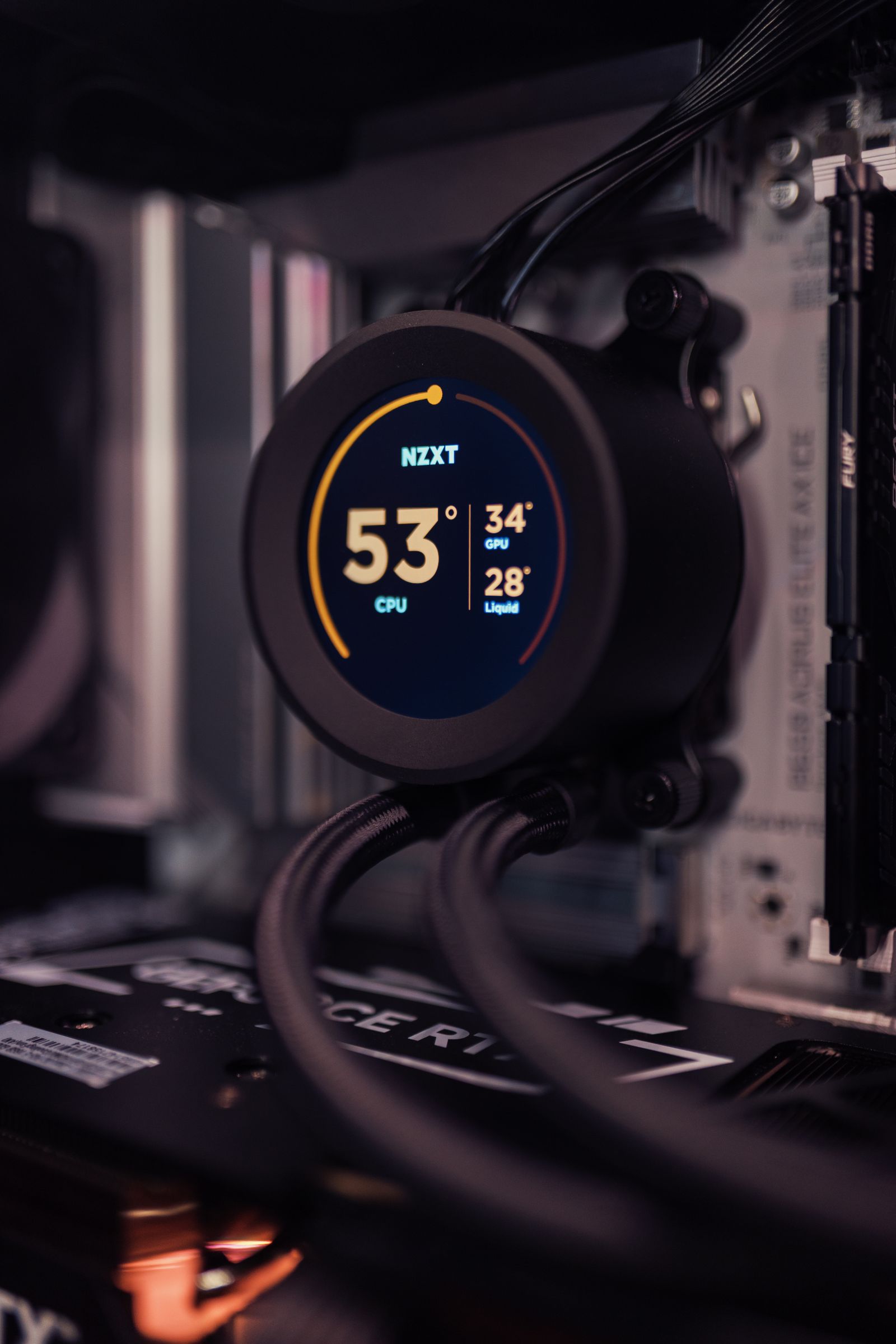
Illustrative image: Unsplash contributor on Pexels
A cold plate can remove a kilowatt from a heater and still struggle with the processor it was designed to cool, because the same total power can be spread across the package or concentrated in a few small hotspots. Thermal test vehicles make that problem measurable before production silicon is readily available, provided they reproduce enough of the chip and package to make the comparison fair.
KLC used its appearance at the 2026 Hon Hai Tech Day to promote thermal test vehicles for AI and high-performance computing, advanced packages, cold plates and liquid-cooling systems. Its public release describes controllable heat sources for chip and wafer layouts, but it does not disclose the die size, heat-flux range, heater-zone count, sensor arrangement, package stack or calibration uncertainty of the devices shown. Those details decide how closely a test represents the eventual processor.
Using a production processor is not always the cleaner experiment. Its workload, internal power management and limited telemetry can make it difficult to repeat precisely the same thermal conditions, while a purpose-built heater can apply a known power map to each cold plate or interface material. That repeatability is valuable, but it only helps if the map represents the device being designed.
The heat map matters as much as total power
A single large resistor is adequate for some early comparisons, though it cannot recreate a concentrated compute hotspot beside a cooler memory region. A plate may remove 800 W in total while one small area runs beyond its temperature limit, which is why more capable vehicles divide the surface into independently controlled heater zones.
A 2026 research platform from the University of California, Berkeley illustrates what that can look like. It uses 140 independently controlled power-transistor heater zones, with resistance-based temperature sensing in each zone. The system can create uniform and localised heat profiles, operate with forced-air or liquid cooling and record its behaviour through an onboard computer. It is a research implementation rather than a specification for KLC’s product, but it shows why spatial control changes the quality of the experiment.
Choosing the pattern is as important as building the heater. A credible die or package model needs to supply the hotspot size and position, peak heat flux and duration, including whether neighbouring regions heat up together. Otherwise, the test may deliver beautifully repeatable measurements of a load the real processor will never produce.
The package sits between heater and coolant
The heat map reaches the coolant through the package, where the die attach, underfill, lid, heat spreader and thermal interface each affect heat flow according to the construction used. Flatness, clamping pressure, bond-line thickness and voiding can make a local temperature much worse than a calculation based on nominal material conductivity would suggest.
A ceramic heater against a cold plate can give a useful comparison of channels and flow rates, but it cannot establish the temperature of the finished processor unless the intervening stack is representative. Chiplet packages make the problem harder, because several heater tiles may reproduce the separate sources while missing the lateral heat flow through their common substrate and lid.
The assembly can also change shape as it heats. If the test vehicle is stiffer or expands differently from the production package, it may maintain good contact where the real device bows away from the plate. That mechanical mismatch can hide an interface problem even when the applied power is correct.
A controlled transient reveals more than a steady state
Steady-state measurements establish the final thermal resistance at a chosen flow and inlet temperature. Real accelerators rarely remain at one power indefinitely, so a test vehicle should also apply steps, pulses and moving hotspots. The resulting temperature curve exposes the thermal capacitance of the package and plate, control-loop delay, coolant transport time and any overshoot when pumps or fans change speed.
The electrical and temperature measurements need to be trusted before the cooling result can be trusted. Heater power is normally derived from voltage and current, while resistance, diode or embedded-sensor measurements provide temperature. Lead resistance, sensor self-heating and conversion accuracy all enter the uncertainty budget, so calibration needs to span the operating range and survive the intended thermal cycling.
Coolant flow, pressure drop and inlet and outlet temperatures complete the experiment. A plate that reaches a lower temperature only after pump power has doubled may be a poor system-level improvement, even if its thermal graph looks impressive. Recording hydraulic performance alongside temperature makes that cost visible.
Where the evidence stops
Even a well-designed thermal vehicle leaves some questions unanswered. It cannot establish processor timing, power integrity or silicon reliability and a hotspot omitted from its programmed map will remain absent from the result. Its conclusions apply to the loads and package construction actually reproduced in the experiment.
A report needs enough detail to let another team judge that representation, including heater geometry and zone maps, power and timing, package layers, interface thickness and clamping, coolant conditions and sensor uncertainty. Without those conditions, a claim such as “1 kW tested” is too thin to support a decision about a dense, non-uniform processor package.
Sources
Photo: Matheus Bertelli / Pexels. Illustrative image. https://www.pexels.com/photo/close-up-of-cpu-liquid-cooling-system-in-pc-34552791/ | https://www.pexels.com/license/