What Toray’s 150°C capacitor demonstration means for inverter cooling
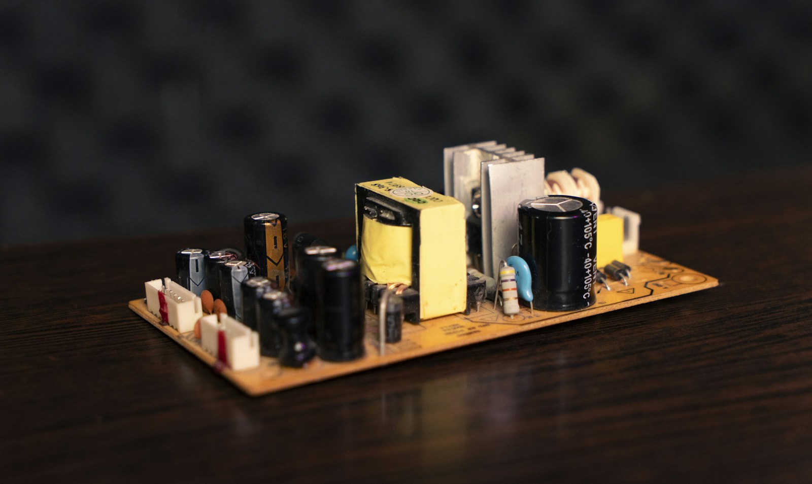
Illustrative image: Abolfazl Pahlavan on Unsplash
A power semiconductor’s temperature rating does not determine how hot an entire inverter can run. The DC-link capacitor has its own thermal limits, influenced by ripple current, internal losses and heat from neighbouring components.
Toray and Nagoya University have demonstrated stable operation of a prototype inverter at 150°C using a film capacitor made with Toray’s proprietary heat-resistant dielectric. Separate thermal simulations indicated that the technology could halve the heat-dissipation structure. That figure concerns the cooling structure, rather than the complete inverter, and is a projected reduction from simulation.
The distinction matters because the capacitor’s operating temperature is not simply the surrounding air temperature. Ripple current produces internal heating. Heat must then pass through the capacitor’s construction and into the surrounding assembly, while nearby power modules can add another thermal load.
TDK’s CAP Thermal design tool models those conditions using the current spectrum, ambient temperature and cooling arrangement. It calculates capacitor self-heating, hotspot temperature and expected service life. This is the relationship Toray’s development could change: a higher permissible capacitor temperature may allow an inverter to meet its operating requirements with less cooling hardware.
The electrical specification still shapes the assembly
Temperature tolerance is one part of that calculation. The DC link also needs sufficient capacitance and voltage capability, alongside the ability to carry the required ripple current over its intended service life. Those requirements determine how many capacitors are needed and how they are arranged.
A TDK ModCap UHP application case illustrates the interaction. It considered a 1,600V DC link requiring at least 1,850µF and 570A RMS, with an ambient temperature of 75°C and power-module terminals at 95°C. The lifetime target was 200,000 operating hours.
For that specification, three UHP units occupied 11.5dm³, compared with 19.3dm³ for five ModCap HF units. The calculation included the current-frequency spectrum and heat transferred from the power modules. The smaller assembly was the result of satisfying the complete electrical and thermal requirement with a different capacitor configuration.
Toray’s prototype addresses temperature tolerance at an earlier stage of development. The simulated reduction would be particularly useful in applications where the mass and volume of heat-dissipation hardware are constrained, including electrified aircraft. It does not establish a production capacitor’s ripple-current capability or service life.
Toray and the university plan further development and evaluation towards commercialisation of capacitors capable of operating at 150°C. The company plans to exhibit the technology at NEDO’s booth during CEATEC 2026, which runs from 13 to 16 October at Makuhari Messe.
Sources
Toray announcement; Toray announcement reproduced by Polymerupdate; TDK capacitor thermal modelling; TDK ModCap application case.