NVIDIA MGX 1.2 puts rack alignment, cooling and power interfaces into the specification
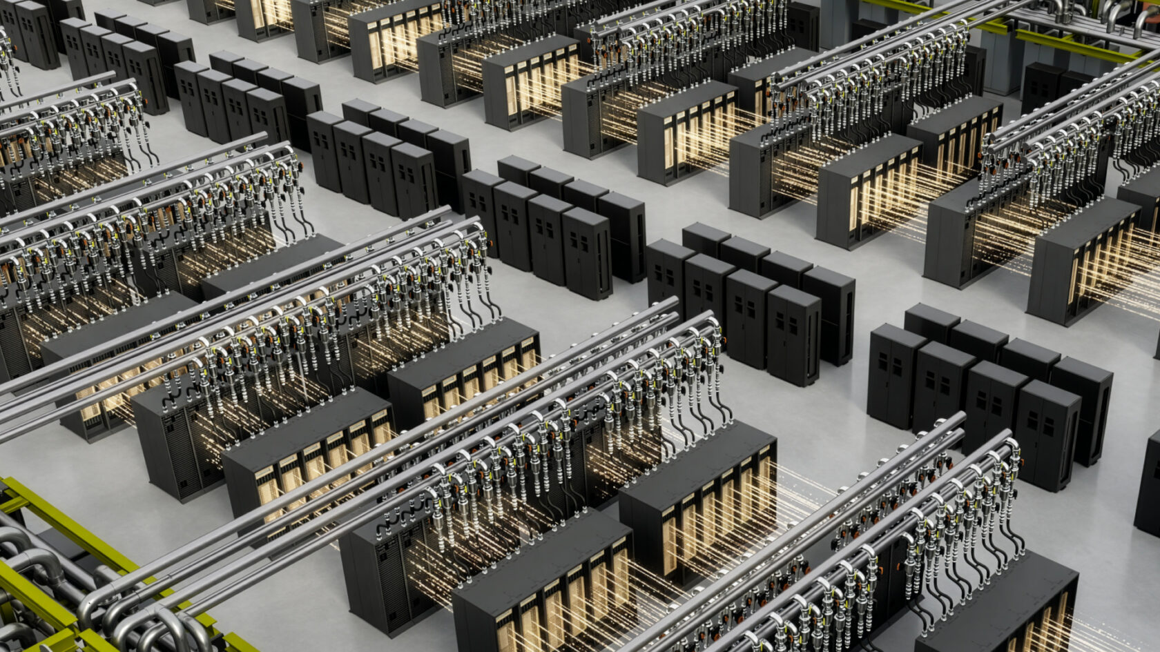
Slide rails, a coolant manifold and electrical contacts must locate the same compute tray correctly. NVIDIA's MGX 1.2 rack specification brings these mechanical, cooling and power interfaces into one documented assembly, including a 5,000A busbar design based on Open Rack V3.
The architecture supports deployments up to 250kW, according to NVIDIA. It adds native 19-inch equipment support and provides configurable I/O bays and fanless, liquid-cooled compute trays.
OCP publishes the MGX Accelerated Computing Rack and Trays Specification V1.2.0 alongside 2D and 3D design files. Its scope includes rack alignment and reinforcement, tray slide rails and manifold mounting.
A common tolerance chain
Sliding a tray into a rack can involve electrical contacts, mechanical location and coolant connections. Each interface has an acceptable alignment range. Their positions must remain compatible as an assembly is manufactured, installed and serviced.
The MGX document sets out blind-mate liquid-cooling features based on OCP's UQD 2.0 specification, including the float mechanism and its mechanical interfaces. A floating connection can accommodate a defined amount of relative movement; the rack, rails and connector mounts still have to keep the assembled tray within that range.
That is why rack alignment features and cooling interfaces appear in the same contribution. A quick disconnect is one component in a larger tolerance chain, rather than an independent guarantee that any tray will mate with any manifold.
Power distribution has the same dependency on the surrounding construction. A 5,000A busbar rating describes a specified design, not an interchangeable piece of metal. Its contacts, supports, thermal requirements and equipment interfaces belong to the documented assembly.
The specification and design files cover different forms of engineering information: the document defines the interfaces and requirements, while the drawings describe the contributed geometry. Use is governed by the stated Open Web Foundation agreement. A tray's compatibility depends on its completed mechanical, electrical and coolant interfaces, not simply on its nominal rack width.