The temperature gradient hidden inside a thermocouple measurement
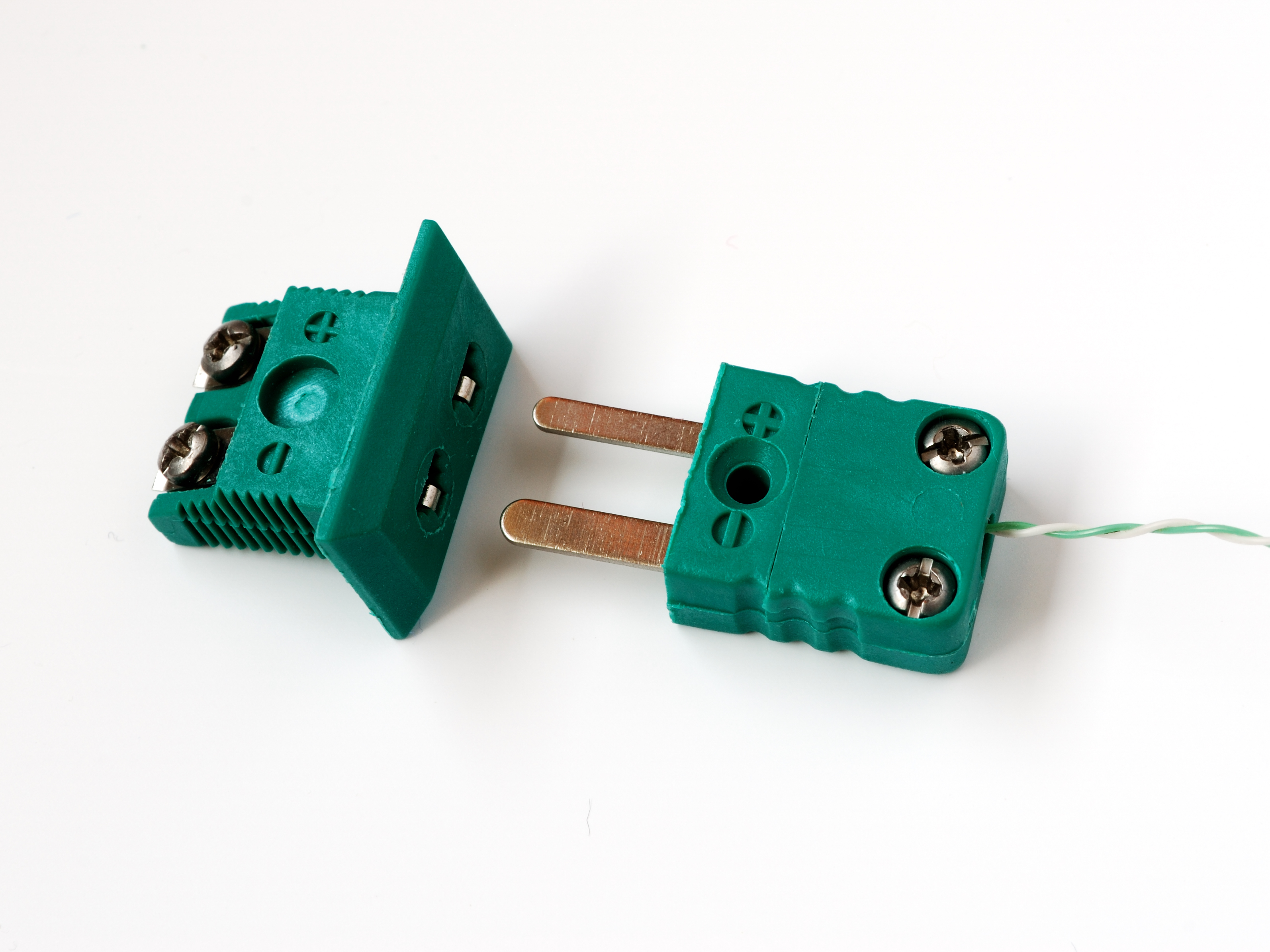
Type K thermocouple connector and socket. Harke / Wikimedia Commons · Public domain
A thermocouple channel can drift through warm-up even while its sensing junction sits in a stable bath. Before adjusting the converter, look at the terminals where the thermocouple alloys meet the copper input circuit. A regulator warming one side of the board or a fan drawing air across the connector can change the temperature there without changing what the compensation sensor measures.
Cold junction compensation works by adding the voltage the thermocouple would have produced between its reference junction temperature and 0 °C. The instrument then converts the corrected voltage to temperature using the appropriate thermocouple curve. That calculation assumes the two alloy-to-copper transitions are at the temperature reported by the compensation sensor. If both terminals warm up together but the sensor stays cooler, the correction is too small for a typical Type K measurement. If one terminal is warmer than the other, a single reading can no longer represent both junctions.
The position of the compensation sensor on the schematic tells you nothing about its thermal surroundings. It may be inside a converter IC warmed by nearby circuitry, or mounted close to the terminal block but separated from it by an air gap. On a bench the assembly may appear stable; once the lid is on, heat has a different path to the enclosure and air may move across the terminals differently. That is why a warm-up test in the assembled instrument is more revealing than a single reading from the open board.
Separate the thermal error from converter drift
- Hold the sensing junction at a stable temperature and log both the indicated temperature and the compensation reading from cold start to thermal equilibrium. Run the test with the enclosure in its normal configuration and nearby circuits operating as they would in service.
- Use electrically insulated contact probes to compare the temperatures at both alloy-to-copper transitions and at the compensation sensor. Change one likely heat source or airflow condition at a time and compare the three readings with the drift in the thermocouple channel. A probe on the plastic connector housing is useful only if it tracks the temperature at the actual transition.
- If the instrument allows it, disable compensation and repeat the warm-up with a stable millivolt input to check the voltage measurement separately. Keep the electrical test setup stable as well, since unwanted junction voltages in the leads can matter at this scale.
If both terminals move together but the compensation sensor follows a different temperature, improve thermal coupling between the sensor and the terminal pair. If the terminals diverge, reduce the gradient across the pair first. Repeat the original test with the enclosure closed and compare the warm-up curves before making any calibration adjustment.
Sources: Analog Devices AN-28: Thermocouple Measurement; Analog Devices: thermocouple measurement and compensation.