A photonic microwave source switched frequency in 27 ns. When is it ready to measure?
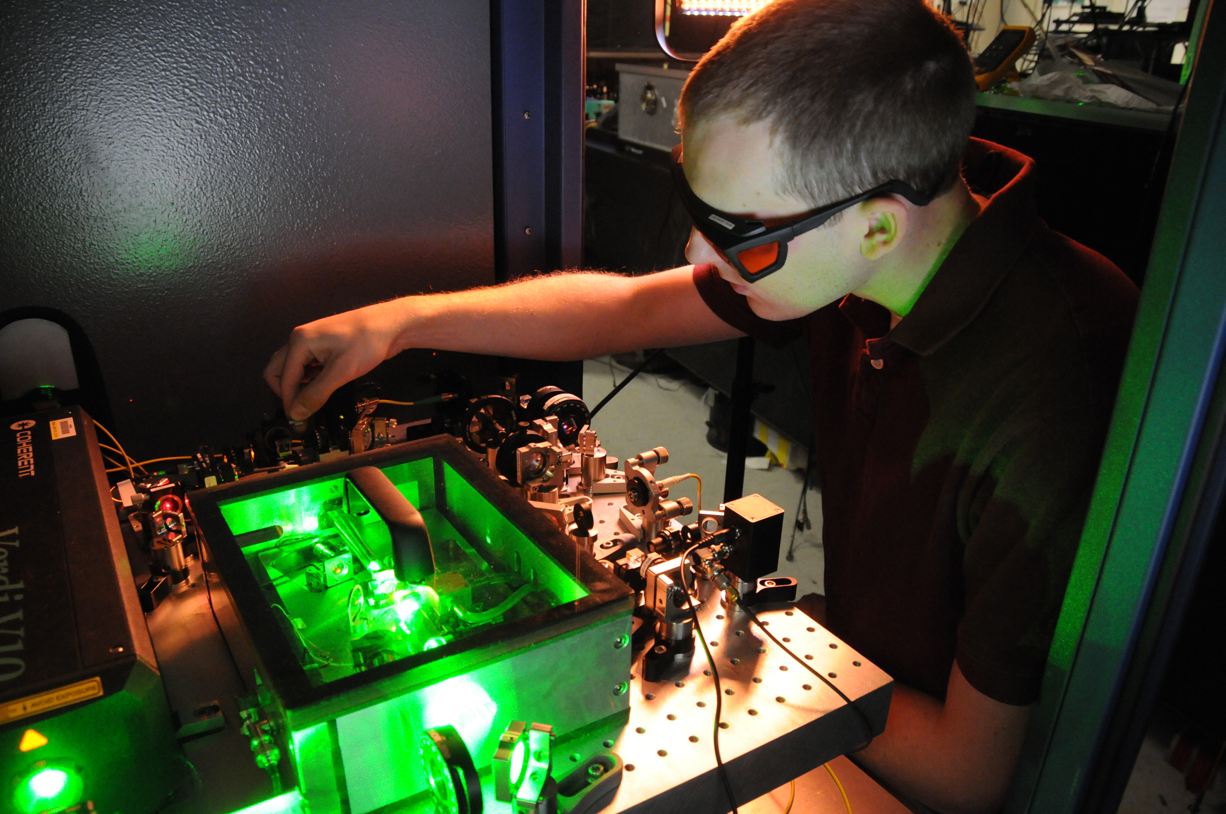
Matt Kirchner adjusts an ultra-stable microwave generator at NIST in an archive photograph. It illustrates optical microwave generation and does not show the oscillator reported in the paper.
Image: Burrus / NIST · NIST reuse terms
A filter can look as though it passes more power than it really does if the measurement is taken while the signal generator is still sweeping across a sharp band edge. It’s an awkward place to save time: a faster frequency change helps, but any change in level or short-lived unwanted signal can show up in the reading as if it came from the filter itself. That’s the context for a result from Tengfei Hao, Tong Yang and colleagues, who reported a 27 ns frequency change in a photonic microwave oscillator along with phase noise as low as −134 dBc/Hz at a 10 kHz offset. The figures describe different properties of the source, so neither tells us on its own how soon the filter can be measured.
In an optoelectronic oscillator, part of the loop that keeps the microwave signal going is an optical path. A long delay in that path can help keep phase noise down, yet the same delay sets a timescale for changes to work through a conventional loop. The researchers’ design makes a frequency change less dependent on the cavity delay, allowing it to move more quickly without giving up the long optical path. That is the change their switching result captures. In the filter example, the wait ends only when the source is steady enough for the test’s own limits on level and unwanted signals.
Phase noise can limit another kind of measurement even when the source has settled. Think of a weak tone close to a much stronger one: the noise around the strong tone at that particular separation helps determine whether the weaker signal can be seen. A value at 10 kHz tells us what the noise was at that offset, while a different separation may give a different result. It’s useful information about the carrier, but it doesn’t describe what happens in the brief interval when the oscillator is changing frequency.
The authors also report a partially integrated implementation on thin-film lithium niobate. Moving some of the functions onto a chip leaves an open question about the optical and electrical hardware that would still have to fit within an instrument, alongside the test conditions needed to compare it with an existing source. The abstract doesn’t put the best phase-noise figure and the switching time under a common test condition. A swept instrument would additionally need to specify the size of the frequency step and the point at which its signal is back within tolerance, because that’s when the next reading can begin.
Sources: Hao, Yang et al., peer-reviewed PIANO research paper; NIST measurement guidance on phase modulation noise and carrier offsets.