How Pickering keeps four test waveforms in step
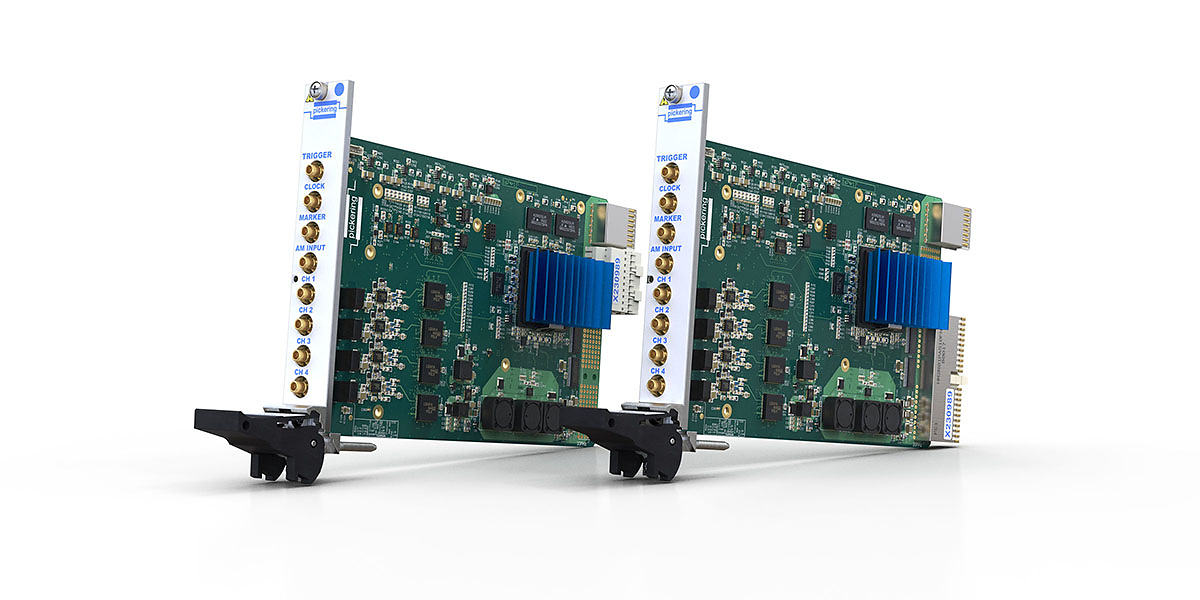
Image: Pickering Interfaces
When a controller compares two sensor signals, a test fixture can make one appear to lead the other even if both waveforms started together at the generator. The two outputs can be right for frequency and amplitude, yet the test still presents the controller with the wrong phase because one signal spends longer getting there.
Pickering Interfaces launched the 41-621 PXI and 43-621 PXIe generators at electronica, with two- and four-channel versions. The four-channel model fits in one 3U slot and gives each output its own 16-bit digital-to-analogue converter, with a 250 MSa/s update rate and a 128 million-sample buffer. Pickering specifies sine waves up to 40 MHz and amplitudes up to 20 V peak to peak into a high-impedance load. The generators use continuous-phase direct digital synthesis and support arbitrary waveforms for stimuli that a simple sine source cannot reproduce.
The modules can synchronise and phase-align channels within a card and across cards, according to Pickering. The product specification lists the 10 MHz PXI clock, an internal clock or an external standard as reference options, with triggering available through PXI and the front panel. The reference sets the timebase and the trigger coordinates when generation begins. Neither accounts for everything between the generator and the point at which a controller sees the signal.
At 10 MHz, a cycle lasts 100 ns. An extra 10 ns of delay in one path would shift its signal by 36° relative to the other. That is an illustration of fixture delay, not a figure for Pickering’s hardware. Cabling, filters or isolation on one channel can introduce an offset after the instrument, and a fixture that changes between builds can change the offset again. Four sources in a slot save space; the phase that matters to the test is the one measured at the controller input.
Sources: Pickering launch at electronica; Pickering four-channel product specifications; Pickering 41/43-621 datasheet