By James Creber · Editorial Tech Update
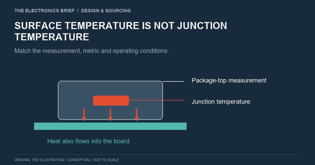
A package surface reads 70°C on the thermal camera. The datasheet permits a much higher junction temperature. There appears to be room to spare, but those two numbers describe different parts of the device.
The surface reading can help estimate junction temperature. It cannot simply be compared with a junction limit and treated as the result. That matters particularly when qualifying a substitute in a board whose cooling arrangement is already fixed.
TI's thermal-metrics note explains that junction-to-ambient thermal resistance, θJA, depends on the test board and environment. A datasheet value should not be assumed to predict behaviour in a different assembly.
The note describes ψJT as a characterisation parameter for estimating junction temperature from the package-top temperature and power dissipated in the device. It is not a true thermal resistance. Its application needs device-specific guidance and suitable measurement conditions; θJC is not an interchangeable substitute.
For illustration, suppose an applicable ψJT is 2°C/W, the package top measures 70°C and the device dissipates 3 W. The estimate is 70 + (2 × 3), or 76°C. These are hypothetical values, not results from a tested component. The 3 W is heat dissipated in that device, not total board input power or power delivered to a load.
The calculation is only as useful as its inputs. Record the component and board revision, enclosure, workload, ambient conditions and measurement method alongside the estimate. Make it clear which temperature was measured and which was calculated.
That record also makes a substitution test worth repeating. If the candidate is measured on a different board, with the enclosure open or under another workload, an apparently better result may not answer the qualification question.
Choose operating cases from the product requirements rather than whichever state is easiest to exercise on the bench. Include the relevant load combinations, duty cycles and surrounding heat sources, and agree the test duration and required margin with the engineer responsible for the design.
Internal temperature telemetry can provide another measurement where available. First establish what the sensor reports and how the manufacturer specifies it. A displayed temperature without that context can introduce another assumption into the comparison.
The useful commercial result is a candidate that meets the required margin in the intended assembly, with evidence the team can reproduce. If it needs a different cooling arrangement or assembly process, include that change in the cost and qualification plan.
A cheaper component can still be a good substitution. The thermal image should help establish that case, with the measurement conditions and calculation attached, rather than leaving the next reviewer to infer it from the colours.
Illustration: The Electronics Brief. Conceptual diagram.