By James Creber · Editorial Tech Update
With the lid off and the access point beside the bench, a wireless prototype can look ready for production. Put the same board inside its enclosure, add the battery and cable assemblies, and there is another test to run.
An integrated antenna makes a module convenient. It does not make the surrounding product disappear from the RF design.
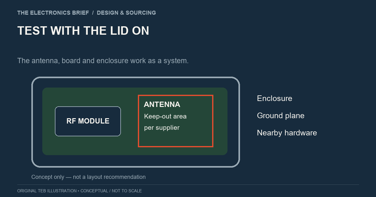
Silicon Labs' WFM200 hardware guide calls for antenna matching to be verified in the final enclosure. It identifies board size, ground plane, shielding, nearby components and plastic enclosures as factors that can affect antenna impedance and radiation pattern.
Those instructions are specific to that module, but the wider integration question is relevant when choosing any wireless assembly: how closely does the finished product follow the conditions under which the antenna was designed and tested?
Carry the supplier's placement and keep-out requirements into the mechanical design. If a bracket, cable or battery moves near the antenna, bring that change back to the RF engineer before it becomes part of the production build.
Use a unit with the intended enclosure material, internal hardware and mounting arrangement. Agree the orientations and operating conditions that matter for the application. A successful link at one distance is a useful observation; it is a limited basis for a range claim.
The test plan needs to cover the application requirement as well as the RF measurements needed to investigate the design. An RF specialist or test laboratory can help define that work where the team lacks the equipment or experience. Decide what constitutes a pass before comparing alternatives, so a convenient demonstration does not become the acceptance criterion.
For its WFM200 design, Silicon Labs recommends provision for external antenna tuning where applicable. Follow the documentation for the chosen module and antenna when deciding what tuning components or measurement access to provide. Leaving room for the recommended adjustments is easier before the layout is released.
Record the qualified antenna, cable, connector and placement. That gives purchasing a meaningful reference when an alternative is proposed. A similar-looking assembly still needs its differences assessed against the design and test evidence.
Also confirm which module approvals and integration conditions apply in the intended markets. The final product needs its own compliance assessment; a module's paperwork should be reviewed as part of that work.
For the project schedule, put the RF review where it can influence the enclosure and tooling decisions. Finding a problem at that point is inconvenient. Finding it after committing to production housings leaves fewer affordable ways to solve it.
Illustration: The Electronics Brief. Conceptual diagram.