RS-485 termination and biasing: seven mistakes that cause unreliable links
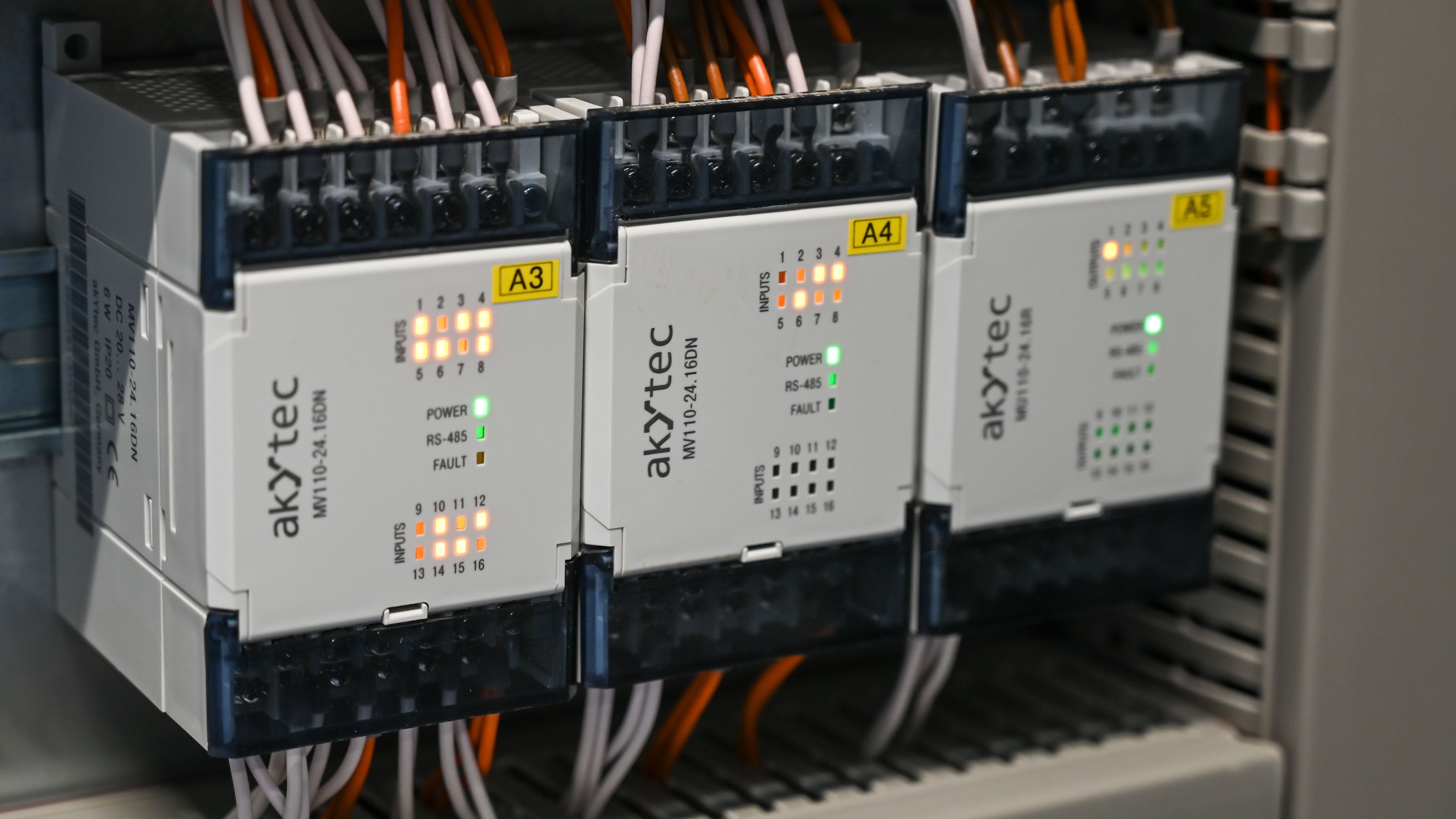
Illustrative image: Unsplash contributor on Pexels
RS-485 defines differential electrical signalling for robust communication across a shared bus. It does not define the application protocol, connector or every aspect of wiring.
Successful links depend on the transceivers, cable, topology, data rate, distance, termination, idle-state behaviour, grounding and protection working as one system.
Many faults remain hidden on a short laboratory cable. Longer installed wiring, additional nodes, electrical noise and ground-potential differences expose the missing margin.
Mistake 1: building a star instead of a bus
The conventional RS-485 network is a daisy-chained trunk with short stubs to each node. A large star creates multiple unterminated branches. Each branch can reflect an edge back towards the junction.
At sufficiently low data rate and short distance, a star may appear to work. That is not proof of margin.
Keep the main cable continuous. If the physical installation requires branching, evaluate repeaters, hubs or transceivers designed for the topology rather than assuming standard termination will repair it.
Mistake 2: allowing long stubs
A stub is the branch from the trunk to a transceiver. Electrically, it is another transmission line.
The acceptable length depends on signal rise time and propagation delay, not only the nominal bit rate. A modern transceiver can have fast edges even when the protocol runs slowly.
Keep stubs short and place the transceiver near the connector. Avoid long PCB traces between the bus connector and the device. Where a connector feeds several boards internally, include those paths in the network model.
Mistake 3: terminating every node
Parallel termination normally belongs at the two physical ends of the bus, with a resistance chosen to match the cable's characteristic impedance.
Adding a terminator at every node excessively loads the drivers and reduces the differential voltage. Leaving the far end unterminated allows reflections.
TI's RS-485 guidance stresses that termination resistors should be placed at the cable ends. Confirm the actual physical ends, which may not be the master and last logical address.
Some short, slow links can operate without termination. That is an engineering decision based on edge rate, cable delay and noise margin, not a default cost saving.
Mistake 4: confusing termination with fail-safe biasing
Termination matches the line to reduce reflections. Biasing establishes a defined differential state when no driver actively controls the bus.
They solve different problems.
External bias resistors pull the two lines towards a known idle polarity. Their values must create adequate differential voltage while accounting for terminators, receiver thresholds, supply tolerance and the number of loads.
If the bias is too weak, noise can move the bus through the receiver threshold. If it is too strong, it consumes current and reduces the active driver's margin.
Many modern transceivers include internal fail-safe receiver behaviour for open, shorted or idle inputs. Read the exact datasheet before deciding that external bias is unnecessary. Devices on the same bus should have compatible assumptions.
Mistake 5: duplicating the bias network
Biasing at several nodes places the resistor networks in parallel. This can increase loading and alter the idle differential voltage.
Use one defined bias location unless the network has been explicitly designed otherwise. Document which node owns it and what happens when that node is disconnected or unpowered.
If field wiring permits different devices to become the network master, the bias strategy must remain valid through every allowed configuration.
Mistake 6: treating differential signalling as ground-free
RS-485 receivers have a permitted common-mode range. Differential signalling helps reject noise that appears on both conductors, but it does not allow unlimited ground-potential difference.
Provide an appropriate reference conductor or isolation strategy. Check shield termination, protective earth, surge environment and the possibility of current flowing through the signal reference.
For long cables between buildings or equipment with different earth systems, galvanic isolation and coordinated surge protection may be necessary. Isolation must include the power arrangement and protection return paths, not just a digital isolator symbol.
Mistake 7: forgetting the cable and protection network
Use a twisted pair with a known characteristic impedance. Keep the pair together through connectors and terminal blocks. Random wire, changing geometry and untwisted sections create discontinuities and reduce noise rejection.
Protection components add capacitance and can distort fast signals. Place them with a short discharge path and select them for the expected surge or ESD environment.
A shield can reduce coupling, but its termination must be designed for the installation. A long pigtail has substantial high-frequency inductance.
Calculate the loading
Traditional RS-485 terminology expresses receiver loading in unit loads. Modern transceivers may present a fraction of a unit load, permitting more nodes, but cable loss, bias networks and termination still consume drive margin.
Add the actual receiver loads and resistor networks. Check the minimum driver output and receiver threshold across supply and temperature.
Do not infer node capacity solely from a headline such as 256 nodes. The real system includes connectors, protection, topology and environmental noise.
Match data rate to distance and edge rate
Longer cables introduce propagation delay and attenuation. Higher data rates reduce the bit interval. Cable quality, transceiver edge shaping and termination determine the useful combination.
Some transceivers deliberately limit slew rate to reduce emissions and reflections on slower networks. That can be more robust than using the fastest available part.
Verify the selected device and cable against the installed distance. Then test with maximum node count, worst allowed cable and representative temperature and supply.
Check half-duplex timing
On a two-wire half-duplex bus, nodes share the same pair. Firmware or hardware must release the driver at the correct time so another node can respond.
Turning off too early can truncate the final bit. Holding the driver too long can collide with the response. Account for UART status, shift-register empty time, transceiver enable delay and cable propagation.
Observe the bus at both ends during direction changes. A local logic-analyser trace may not show the analogue problem on the cable.
A commissioning checklist
- Bus is a continuous trunk rather than an uncontrolled star.
- Stubs are short relative to edge speed.
- Termination is fitted at the two physical ends only.
- Cable impedance and terminator values are compatible.
- One deliberate fail-safe bias strategy is documented.
- Common-mode voltage remains within transceiver limits.
- Reference, shielding, isolation and surge paths are defined.
- Driver turnaround timing is verified.
- Maximum cable, node count and worst operating mode have been tested.
RS-485 reliability comes from managing the analogue network underneath the protocol. If a link only works after reducing the bit rate, moving a cable or touching the ground connection, it is reporting a physical-layer problem that still needs to be understood.
Technical sources
- Texas Instruments, RS-485 basics: termination.
- Texas Instruments, External fail-safe biasing of RS-485 networks.
- Texas Instruments, RS-422 and RS-485 standards overview and system configurations.