PCB manufacturing checks: six gaps a DRC pass can miss
Illustrative image: ThisIsEngineering on Pexels
A PCB design and its manufacturing release can drift apart during the final revisions, particularly when component substitutions or changes to the assembly variant affect several files. The discrepancy may sit between the BOM, placement data and fabrication outputs even though the design itself passes its rule checks.
That makes the release package worth examining as a separate engineering deliverable. The CAD project describes the design being worked on, while the exported files tell the factory what to build. Comparing the two exposes a different set of problems from those found by the design rule checker, including missing manufacturing information and instructions that no longer match the intended variant.
Six areas account for the scope of this review, from the fabrication data through to the information needed for repeat orders.
1. Gerber and drill files can disagree with the intended board
Layer alignment, units and viewing conventions affect how fabrication data is interpreted. Eurocircuits puts “Do not scale your data” first in its rules for preparing files, alongside requirements for consistent offsets and viewing layers from top to bottom. Opening the exported copper, solder mask, outline and drill data in a separate viewer makes discrepancies visible without relying on the CAD project to reconstruct them. [1]
The comparison extends to the stackup and mechanical drawing. Plated and non-plated holes need to be distinguishable, while slots and cutouts need a definition the chosen fabricator accepts. Where a drawing and the manufacturing data differ, an engineering query can resolve the intention before either version becomes a physical board.
Mechanical fit adds another layer to this. A connector may agree with its PCB footprint yet leave too little space for the mating plug, latch movement or a nearby screw head once the enclosure is assembled. The board outline alone cannot show those restrictions.
2. Design rules depend on the manufacturing process
A clean DRC result establishes that the layout satisfies the rules loaded into the tool. Whether those rules match the purchased manufacturing service is a separate question, especially when a project moves to another supplier or changes its layer structure.
Track and gap limits, annular rings, drill sizes, solder mask features and distances from copper to the board edge all have process implications. Eurocircuits separates pattern and drill classifications because the geometries affect manufacturing capability and cost; another supplier’s service may have different limits. [2]
Stackup changes can also affect controlled impedance. Dielectric thickness, material properties, copper geometry and the fabricator’s compensation interact, so matching overall board thickness leaves several electrical variables unresolved. Clearance and creepage introduce a further distinction: the insulation design and applicable safety requirements determine the necessary spacing, independently of the smallest gap the factory can etch.
3. A package name does not fully define a footprint
Component substitutions can retain a familiar package description while changing details that matter to assembly. Comparing the exact manufacturer part number and package drawing with the land pattern brings pin numbering, exposed pads, paste apertures and orientation into the same review.
Exposed pads are particularly dependent on the selected device. Their electrical connection, paste coverage and treatment of thermal vias affect whether the assembled part performs as intended. A generic library footprint may need adaptation to those requirements.
Eurocircuits’ assembly guidance calls for clear orientation information for symmetrical packages and polarised through-hole parts. Position and pin 1 alignment are separate checks because a component can be centred on its footprint while rotated incorrectly. Agreement between the placement file, assembly drawing and board markings removes that ambiguity from the handover. [3]
4. Connectivity checks leave current path questions open
A connected net can still have an unsuitable physical route. For example, a signal crossing a break in its reference plane can force its return current to take a longer path at high frequencies, while a nearby decoupling capacitor can have an inductive connection through its pads, traces and vias.
The device’s layout guidance helps identify which routes deserve closer examination, including switching current loops and the relationship between sensitive analogue connections and their returns. Analog Devices’ AN-1119 illustrates the importance of those physical current paths in power supply layout. [4]
Tracing a few critical circuits through the actual board gives the release review an electrical purpose beyond confirming that the files contain the right layers.
5. BOM and placement data need the same assembly variant
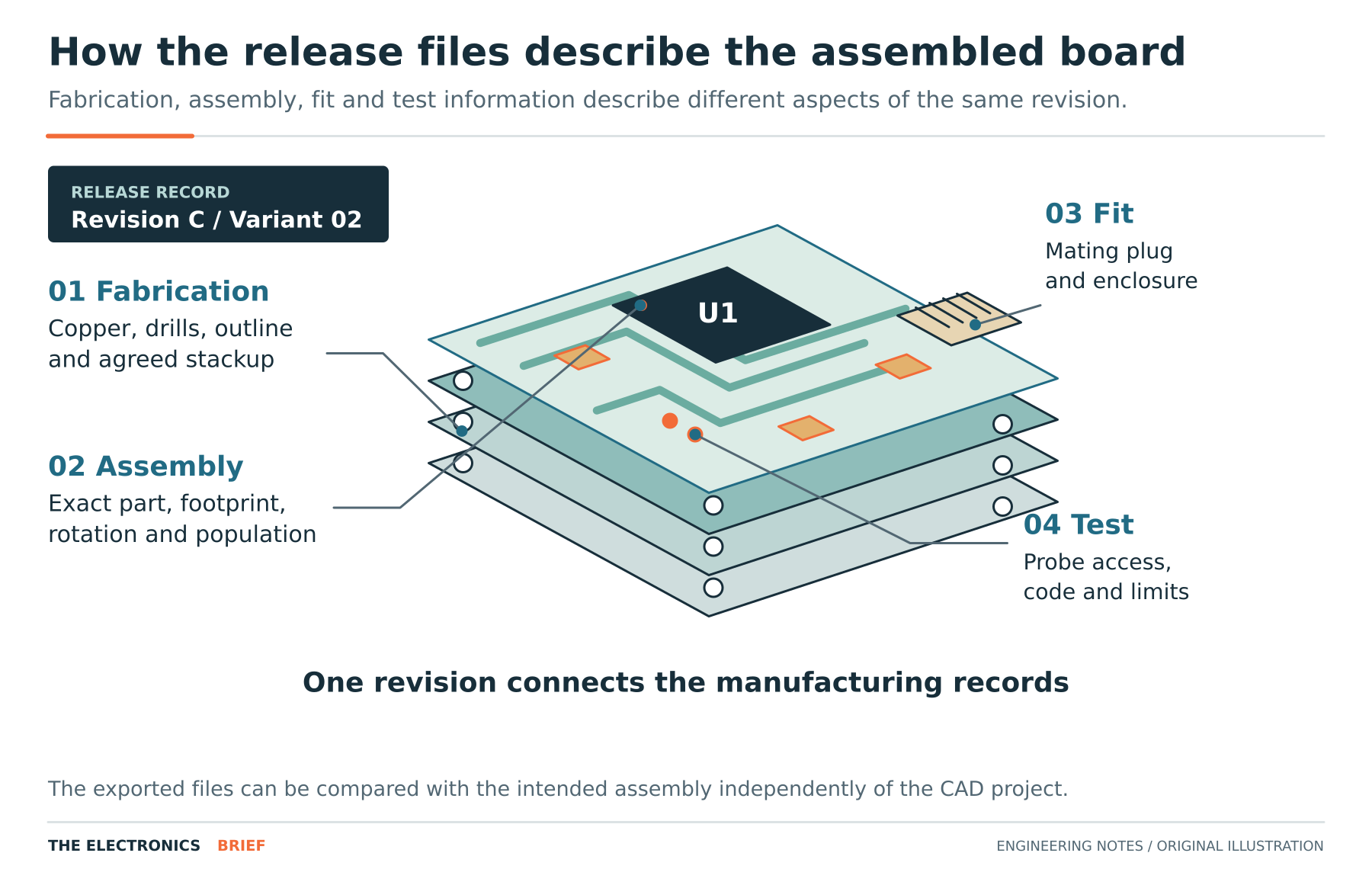
The BOM and placement file describe different aspects of the same assembly, which creates opportunities for them to diverge when a variant changes. Eurocircuits requires both as assembly inputs. Comparing reference designators, quantities, population status and orientation against the released variant establishes whether the exported pair still agrees. [5]
A “do not fit” instruction belongs in that comparison, along with any component characteristics the design depends on. A generic 10 kΩ description may be sufficient in one position but inadequate where voltage coefficient, pulse behaviour or package construction matters. The purchasing information needs enough detail to preserve that distinction.
Programming, calibration and test requirements also form part of the build. Fixture access can change when a connector or bracket moves, even if the test pads remain present in the PCB data.
6. Manufacturing queries become part of the release record
A fabricator or assembler may propose a change after reviewing the package. Recording the agreed response against the revision keeps the resulting production instruction connected to its engineering approval, particularly where the change affects materials, tolerances or assembly treatment.
A clearly identified set of files, variant and agreed exceptions then gives the next order a dependable starting point. This is where the release record earns its keep: months later, the factory and the design team can establish what was actually built without reconstructing a conversation about the first batch.