ICT vs flying probe vs functional test: which PCB test method do you need?
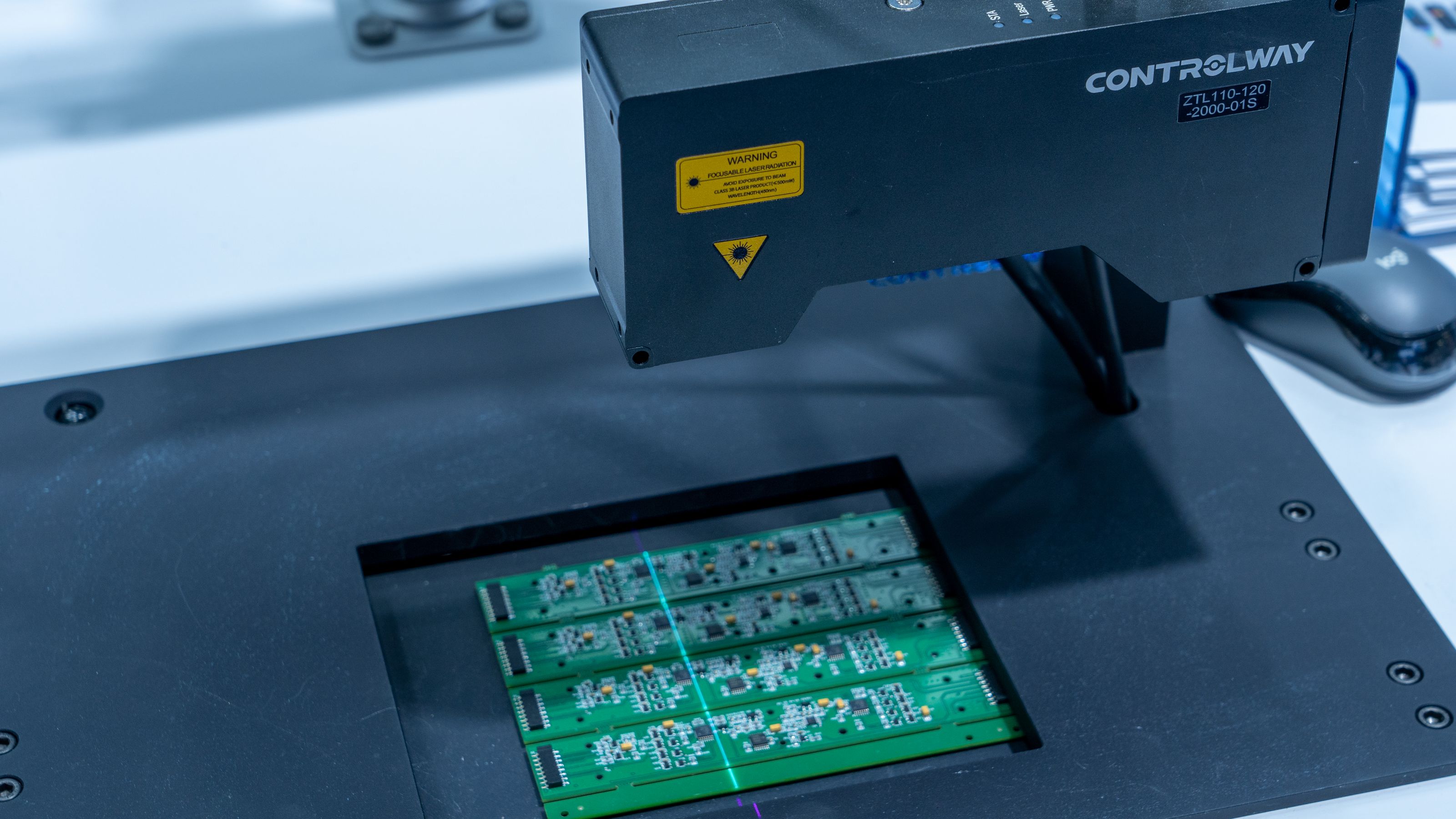
Illustrative image: Unsplash contributor on Pexels
A powered PCB that performs its main function has passed an important test. It has not necessarily proved that every component value, solder joint and unused interface is correct.
Equally, a board that passes an in-circuit test may still fail to boot because the firmware, system interaction or functional requirement lies outside that test's coverage.
Production testing should begin by defining likely defects, required coverage, acceptable cycle time and the information needed when a unit fails.
What in-circuit test does
Traditional in-circuit test, or ICT, uses a fixture commonly described as a bed of nails. Spring-loaded probes contact test pads or accessible nodes while the system measures the assembled board.
Depending on the board and tester, ICT can detect:
- shorts and opens;
- missing components;
- incorrect resistor or capacitor values;
- diode and transistor orientation;
- selected device faults;
- programming or boundary-scan conditions.
Because the fixture makes many contacts at once, ICT can be fast and well suited to volume production. It also offers useful fault localisation. A failure may point towards a particular node or component rather than simply reporting that the product does not work.
The main cost is the fixture and programme development. PCB changes can require fixture modification. Dense boards, limited test access and components connected in parallel can reduce coverage.
What flying-probe test changes
A flying-probe system moves a smaller number of programmable probes between test points. It performs fixtureless or minimally fixtured electrical testing based on CAD and board data.
The approach is attractive for prototypes, new-product introduction and lower volumes because it avoids the time and cost of a dedicated bed-of-nails fixture. The programme can usually be changed more easily when the layout changes.
The trade-off is speed. Moving probes sequentially takes longer than contacting many nodes at once. Mechanical access and board geometry still limit what can be reached.
Flying probe is often useful for:
- prototype and engineering batches;
- low-to-medium production volumes;
- early builds before the design is stable;
- boards whose fixture cost is difficult to justify;
- fault isolation before functional test.
Keysight's comparison of flying probe and ICT describes the same broad trade-off: flexibility and lower fixture commitment against the throughput advantage of a production ICT fixture.
What functional test proves
Functional test powers the board or product and exercises its intended behaviour. It may apply inputs, run firmware, operate interfaces and measure outputs.
It can prove functions that unpowered structural tests cannot, including:
- processor boot;
- analogue measurement accuracy;
- communications performance;
- power sequencing;
- sensor or actuator behaviour;
- user-interface operation;
- system-level firmware and calibration.
Functional test is close to the customer's experience, but it may provide weak fault diagnosis. A board that does not boot could contain a solder short, wrong oscillator, corrupted firmware, missing power rail or faulty processor. Without additional observability, the result is simply fail.
Functional coverage also depends on the test design. An output toggling once does not prove performance across its range.
Comparison at a glance
Dedicated fixture
- In-circuit test: Usually substantial
- Flying probe: Low or none
- Functional test: Application dependent
Test speed
- In-circuit test: Usually fastest at volume
- Flying probe: Slower
- Functional test: Varies widely
Design-change flexibility
- In-circuit test: Lower
- Flying probe: High
- Functional test: Medium
Structural fault isolation
- In-circuit test: Strong
- Flying probe: Strong but access dependent
- Functional test: Often limited
Powered behaviour
- In-circuit test: Limited or optional
- Flying probe: Limited or optional
- Functional test: Core purpose
Best fit
- In-circuit test: Stable higher-volume production
- Flying probe: Prototypes and lower volumes
- Functional test: Every stage where function must be proved
This table is directional. Modern platforms can combine techniques, programming, boundary scan and powered measurements.
Volume is not the only decision
The simple rule that flying probe is for low volume and ICT for high volume is useful but incomplete.
Consider the cost of a missed defect and the cost of diagnosing a failed functional test. A complex, high-value board produced in moderate quantities may justify strong structural coverage. A simple high-volume board may be tested adequately with carefully designed functional and inspection steps.
Calculate:
- fixture and programme cost;
- expected design revisions;
- test cycle time;
- line throughput;
- operator involvement;
- likely defect rate;
- repair and diagnosis time;
- cost of an escaped fault;
- product lifetime and repeat orders.
The break-even point depends on the complete production process.
Test access must be designed in
Test strategy should influence layout before the PCB is released.
Provide accessible pads for important nets, power rails, programming, reset and communications. Agree pad size, spacing and keep-out requirements with the manufacturer or test provider.
Avoid placing probes where they can damage fine features or interfere with components. Consider access from one or both sides and the mechanical support needed to prevent board flex.
If physical access is impossible, boundary scan or built-in self-test may recover some coverage, but these require compatible devices and deliberate design.
Inspection and electrical test complement each other
Solder-paste inspection, automated optical inspection and X-ray can detect assembly features that electrical tests may miss or diagnose poorly. Conversely, a visually acceptable joint can still be electrically faulty.
Build a coverage map across:
- incoming component control;
- paste and placement inspection;
- optical or X-ray inspection;
- unpowered structural test;
- programming;
- powered functional test;
- calibration and final product test.
The purpose is not to test the same easy feature repeatedly while leaving a critical function unobserved.
Golden boards and fault insertion
A known-good reference board helps verify a fixture and functional setup, but it cannot prove fault coverage on its own.
Where practical, insert representative faults or use a fault-insertion board. Confirm that the process detects missing parts, incorrect values, opens, shorts, wrong firmware and calibration errors that matter to the product.
Track false failures too. An unstable test wastes capacity and can encourage operators to bypass genuine problems.
Plan data and traceability
Define what result is stored against each serial number or batch. A simple pass/fail may be sufficient for one product. Another may require measured values, calibration coefficients, firmware version and fixture revision.
Use test limits derived from the product requirement and process capability. Avoid limits so tight that normal measurement uncertainty rejects good boards, or so wide that a drifting process remains invisible.
Analyse failure patterns. Repeated faults at one component or placement location can reveal a design, supplier or process problem that individual repair records conceal.
A practical selection path
Use flying probe when the design is changing, volume is limited or early structural feedback matters more than seconds of cycle time.
Invest in ICT when the design is stable, test access is strong and production volume or diagnosis savings justify the fixture.
Use functional test where the powered behaviour, firmware and system interfaces must be demonstrated. In many products it is required regardless of the structural method.
The strongest production plan often uses flying probe during introduction, moves to ICT when volume stabilises and retains a focused functional test throughout. The exact combination should be based on coverage and economics rather than habit.
Technical sources
- Keysight, Flying probe testing versus in-circuit testing.
- Keysight, A primer on test options.
- Keysight, in-circuit test guidance for manufacturing.