Why a precision ADC can give the wrong answer after switching channels

Illustrative image: Sven Alleblas on Unsplash
The second reading looks sensible. The first one does not. If that happens after an ADC changes channels, it is tempting to blame firmware or discard a sample and move on. The analogue input may simply not have reached its new value when the converter sampled it.
A multiplexed acquisition system asks one signal path to handle a sequence of voltages. A channel near the bottom of the range may be followed by one near the top. The driver, filter and sampling network then have a finite interval to respond to that change, and their previous state matters.
Analog Devices’ guidance on precision converter front ends explains the competing demands. A filter helps limit noise and manage the disturbance from a sampling input, but its resistance and capacitance also affect settling. The sampling capacitor has to acquire charge through a real source impedance; it is not connected to an ideal, instantly responding voltage source.
How much time is enough?
Take a deliberately simplified example: a 16-bit ADC with a 5V input span, a full-span channel step and a front end that settles as a single first-order response with a 200ns time constant. These are hypothetical values, not specifications or test results for a particular converter.
One count is 5V divided by 65,536, or about 76.3µV. Settling to within half a count requires the remaining error to fall below roughly 38.1µV. For this model, the residual error is the initial 5V step multiplied by exp(−t/τ).
After 2µs, ten time constants have passed. That sounds comfortable, yet the residual is still about 227µV: almost three counts. Reaching half a count takes approximately 2.357µs, or 11.78 time constants.
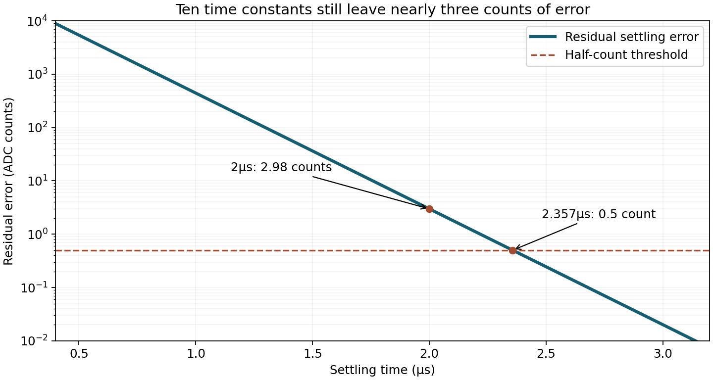
The threshold in the graph is only a settling-error allowance. It says nothing about offset, gain error, noise or non-linearity, and a real amplifier may spend part of the interval slewing before it enters the behaviour represented by this simple model.
Use the acquisition interval, not the headline sample period
The time between output samples is not necessarily the time available for the input to settle. A converter may devote part of that period to conversion and provide a much shorter acquisition window. The relevant interval depends on its architecture and timing requirements.
Multiplexer switching adds another event to the sequence. Charge from the preceding channel, the external filter and the converter’s sampling input can all influence the transient. The multichannel system therefore needs to be evaluated using the actual channel order and timing, rather than a single channel held at a steady DC voltage.
A useful diagnostic comparison is a sequence that alternates widely separated input levels against one that repeatedly samples the same level. If the first result after switching differs systematically from later results, settling deserves investigation. That observation alone does not identify which part of the signal path is responsible.
Averaging is not a dependable cure for this error. It can reduce random variation, but a repeatable shortfall after each channel transition remains a bias in the sequence. Nor is discarding one sample a universal fix: the behaviour changes with source impedance, filter values, signal step and the converter’s acquisition timing.
The worked example can be reproduced with t = τ × ln(2^(N+1)) for a full-span step settling to half a count in an ideal N-bit, first-order system. With N = 16 and τ = 200ns, the result is 2.3567µs.
Sources: Amplifier and RC filter design; Multichannel acquisition performance; Image source.