How a smartphone flash turns battery power into a burst of light
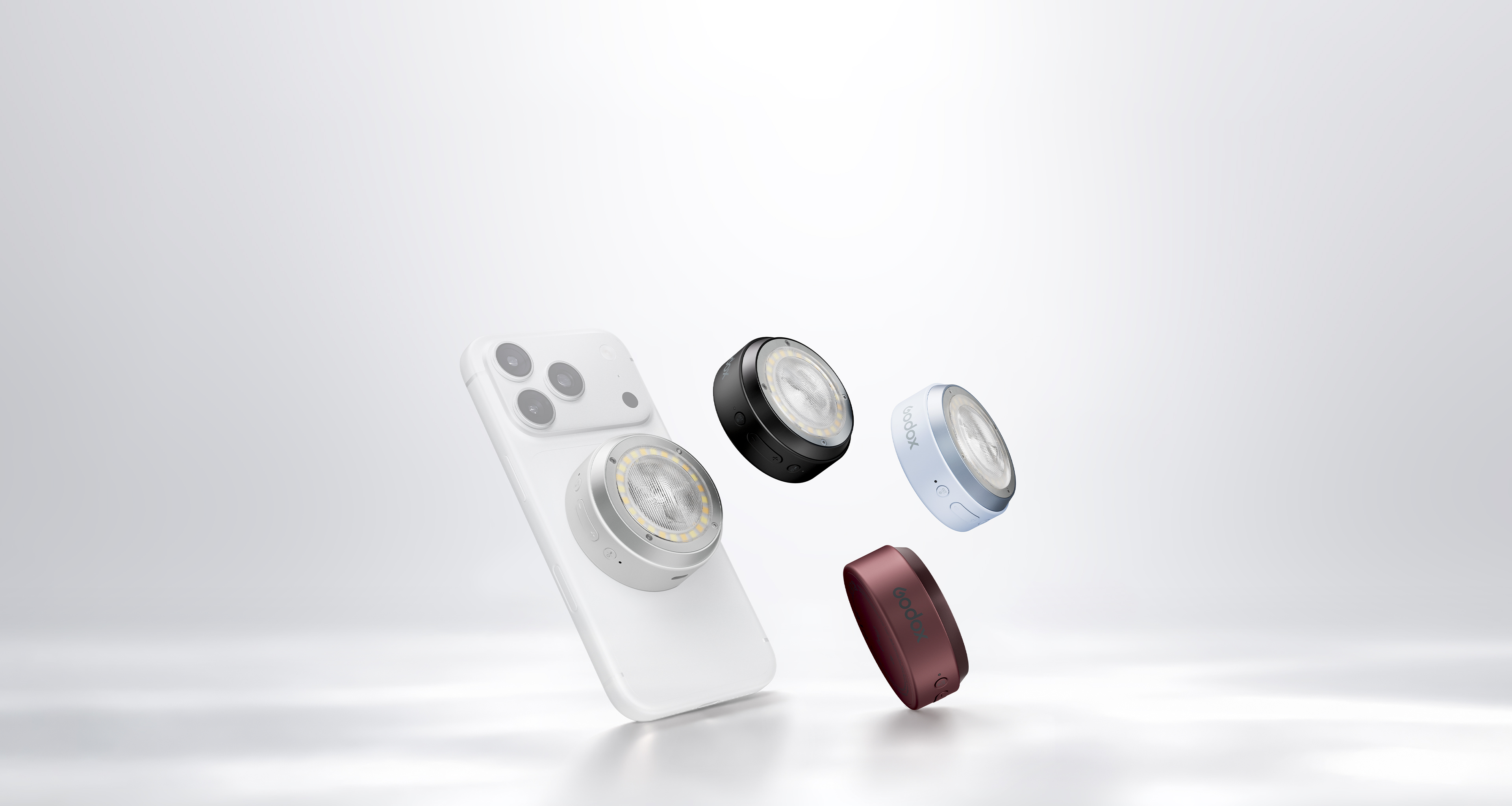
Image: Godox
There is a conspicuous pause between a full-power flash and the moment a flashgun is ready again. That pause is the power electronics doing its work. Energy has to be collected slowly enough for a small battery to supply it, then made available quickly enough to illuminate a photograph.
Godox’s A2 packages that process into a smartphone accessory. It attaches magnetically, supports TTL and manual control through the Godox Camera app, and includes a separate bicolour LED for continuous lighting. The xenon flash and the LED serve different purposes, even though they share the same small enclosure.
Inside a conventional xenon flash circuit, a converter raises the battery voltage to charge a storage capacitor. A trigger circuit initiates conduction through the gas-filled tube, allowing the stored charge to produce the light pulse. An IGBT can control the discharge, ending it once the required amount of light has been delivered. TI’s photoflash design guidance describes this combination of charger and discharge control; it is a reference architecture, rather than a teardown identifying the A2’s components.
The energy calculation explains the attraction. A hypothetical 100µF capacitor charged to 300V stores 4.5 joules, using E = ½CV². Release that stored energy over a short interval and the instantaneous electrical power can be far above the battery’s continuous output. The capacitor acts as an energy reservoir between the two timescales. Those example values are illustrative, not Godox specifications, and electrical energy stored is not identical to useful light emitted.
The charging circuit then has to replenish the reservoir. Godox specifies approximately two seconds for a full-power recycle and around 400 full-power flashes. At lower output, less energy is required for each exposure. Manual control runs from full power to 1/128 in one-third-stop increments; the published guide number is approximately 15 at ISO 100.
Getting that light into a phone photograph brings another engineering problem. With a rolling shutter, sensor rows begin their exposures at different times. Android’s camera documentation explicitly describes the time offset between the first row and the end of the row sequence. A pulse timed correctly for one part of the sensor can therefore miss another part unless the exposure and illumination are coordinated.
The nominal shutter speed does not describe the whole sequence. A short exposure for each row can coexist with a longer interval over which the full image is scanned. To judge synchronisation, the capture mode and the sensor’s timing have to be considered together.
Godox advertises high-speed synchronisation up to 1/8000s through its supported camera setup. The specification describes the synchronised capture capability, separately from the duration of the emitted flash. The published information does not identify the exact pulse waveform used to produce that result.